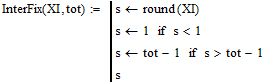
These are general purpose transmission line functions for engineers and HAMs. They are intended for zero loss, low loss, and medium loss transmission lines. Nearly all circuit problems can be solved by applying one or more of these five formulas:
If you find any errors or better formulas, please report them to kq6qv@aol.com. This worksheet was prepared using Mathcad 14, but saved in a format supposedly compatible with Mathcad 11. The worksheet is intended for productive usage, not teaching. It is donated to the public domain. You may distribute it and use it freely. If you try these functions, send me a note and tell me how they worked out.
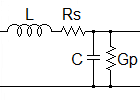
L = inductance per unit length
C = capacitance per unit length
Rs = series resistance per unit length
Gp = parallel conductance per unit length
(These can be rewritten in forms that look very different but are not. They are often written with trig or exponential functions instead of hyperbolics, and they sometimes appear with tangents in place of sines and cosines. They are derived from second order differential equations, but while this is interesting, it does not help you solve any problems.)
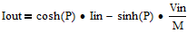
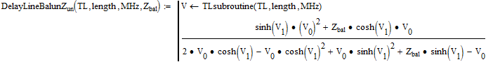
The five equations accurately portray standing waves and exponential loss through dissipation. The only thing they do not handle is unbalanced currents and radiation. The five formulas are encoded in these five functions:
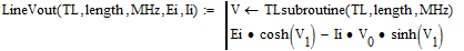
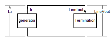
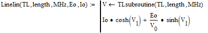
LineVout -- find the output voltage, given the input voltage and current.
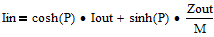
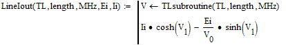
LineIout -- find the output current, given the input voltage and current.
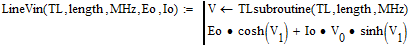
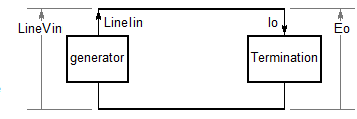
LineVin -- find the input voltage, given the output voltage and current.
LineIin -- find the input current, given the output voltage and current.
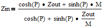
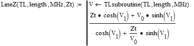
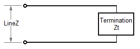
LineZ -- find the input impedance, given the terminating impedance.
1. All lengths and diameters are measured in meters. (In many cases the units are irrelevant if they are consistent.) MKS is standard, but frequency is entered in MHz.
2. There is no radiation loss, no unbalanced current, no leakage through the shield.
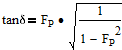
3. The series resistance is proportional to the square root of frequency.
4. The A.C. dielectric loss is proportional to the frequency.
5. You may specify the D.C. dielectric leakage conductance. It is usually insignificant.
6. Most of the functions assume no ferromagnetic materials are present (mr = 1).
7. All voltages, currents, and impedances are complex numbers.
8. The line parameters Zo, vf, L, C, Rs, Gp, er, r, and tand should be entered as real numbers. The functions have not been thought out for complex values of these.
9. Zo and L of any transmission line will vary slightly with frequency since the skin effect causes the effective diameters of wires to change. The circuit solving functions do not automatically compensate for that. So you will want to determine Zo and L for the center of the "band" you are working in. See the functions Lcoaxial and Ltwinlead.
10. This worksheet is intended for zero loss, low loss, and medium loss transmission lines, including all the common line types. Some of the functions will not work well for very high loss lines. (If you want to model coax in which the foam is full of water, these functions are not intended for that.)
With these five functions, you can solve a transmission circuit problem like it is a black box. Then the only reason you would need an intuitive understanding of transmission lines is so that you can propose a circuit that might work.
Some problems come up: Such functions would require 10 or more parameters to be completely general, and there is more than one approach to describing a transmission line.
Typical projects employ only 1 to 3 types of transmission lines. This spreadsheet uses separate functions to define line types, giving each type a name. Those names are fed to the above five functions, reducing the parameter count to 4 or 5. The line type creation functions are:
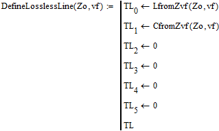
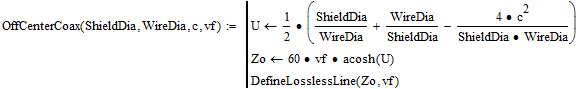
DefineLosslessLine -- define a lossless transmission line, given only the impedance and velocity factor.
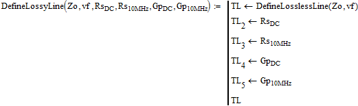
DefineLossyLine -- define a transmission line, given Zo, vf, Rs, and Gp.
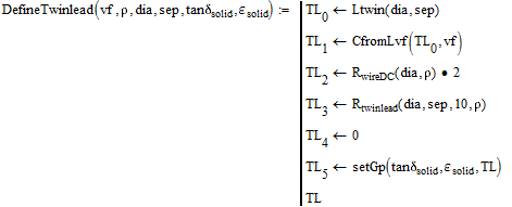
DefineTwinlead -- define a twinlead transmission line. *
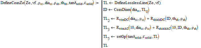
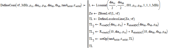
DefineCoax -- define a coaxial transmission line. *
* This function determines the series resistance and shunt conductance from the frequency and the other line parameters.
To reference these functions from another Mathcad document, click Insert>Reference, and browse for TransmissionLines.mcd . The EXCEL and MATHCAD versions can be downloaded from :
http://www.hdtvprimer.com/KQ6QV/HomePage.html
______________________________________________________________________________________________
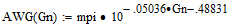
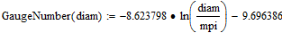
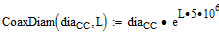
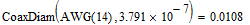
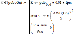
(Normally the name of a function describes its output. AWG is the only function here for which the name describes the input.)
A common published value for tandPE is 0.00031, but common cables seem to model better with a value of 0.00064.
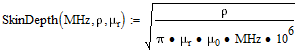
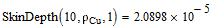
These formulas are for the skin effect in isolated round wires. The formulas are derived at http://www.hdtvprimer.com/KQ6QV/TLderivations.html
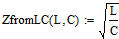
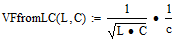
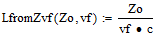
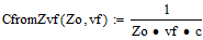
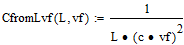
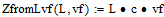
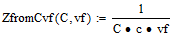
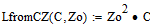
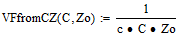
if you know any two of L, C, Zo, or vf, you can find the others. These 12 functions will not work for high loss lines (unless L, C, Zo, and vf are complex numbers).
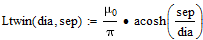
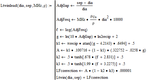
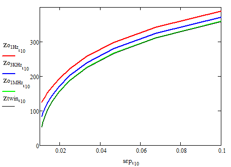
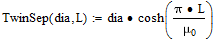
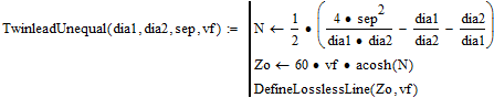
Ltwin is usually accurate, but is seriously wrong at low frequency.
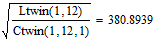
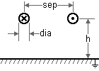
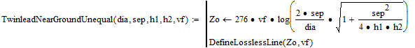
Use Ltwinlead when in doubt. Ltwinlead is usually within 1% for all frequencies and all spacings down to sep/dia of 1.01, assuming sep << l. See Note 3.
L and C are "per meter".
dia and sep are in meters.
MHz is the frequency. L changes very little with frequency, so just a rough estimate of the frequency is required here. The change with frequency above 1 MHz is seldom significant.
r is the wire resistivity. It seldom affects L significantly.
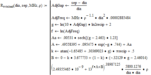
Ltwinlead and Rtwinlead are the result of hand-fitting curves to data from atlc2. Each atlc2 run employed 13000 conductor pixels, producing 13000 equations to solve.
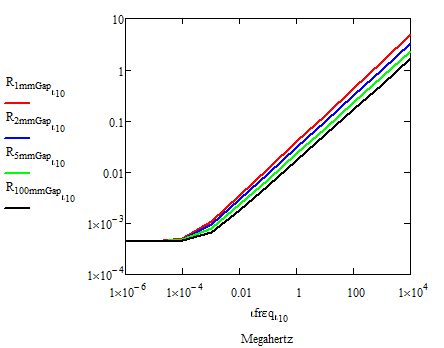
Rtwinlead is usually accurate to 1% for all frequencies and all spacings down to sep/dia of 1.01. See Note 3.
Note 3: Ltwinlead and Rtwinlead are accurate to better than 1% except in the transition-to-DC region. For most twinlead this is from 100 Hz to 10 KHz. In this region the formulas are in error by more than 10% at extremely close wire spacings.
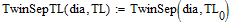
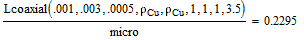
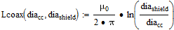
Lcoax is accurate at high frequency, but wrong at low frequency.
Use Lcoaxial when in doubt.
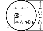
diacc is the diameter of the center conductor.
th and diash are the thickness and inner diameter of the shield.
mcc, mdi, and msh are relative permeabilities.
This formula is derived at http://www.hdtvprimer.com/KQ6QV/TLderivations.html
Lcoax and Ccoax are very accurate above 1 MHz.
L and C are "per meter".
diacc and diashield units irrelevant if consistent.
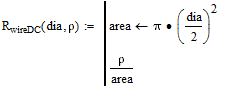
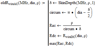
oldRwireAC is the usual formula for wire A.C. resistance, but it is poor in the common case where the skin effect depth is nearly equal to the wire radius.
RwireAC is near perfect for coax (except when the skin depth breaches the steel of a copper clad steel wire), and fair for twinlead when the wires are far apart.
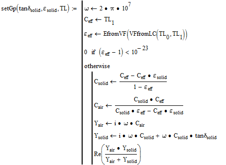
Computes the dielectric loss at 10 MHz.
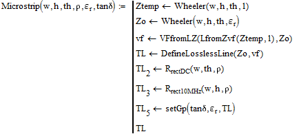
TL is the transmission line type, which is constructed but not fully complete. (Define the transmission line type before calling setGp.)
tandsolid and esolid are for a solid block of the dielectric material, even if the transmission line has foam. The velocity factor will be used to determine how much air is present in the dielectric, and the dielectric loss will be adjusted accordingly. This formula works for any dielectric-air mixture. (The conductance is modeled as two capacitors in series, one with a solid dielectric and one with air.) esolid is a relative value (a number close to 1).
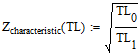
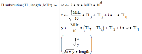
TL0 = inductance per meter
TL1 = capacitance per meter
TL2 = series resistance per meter, DC
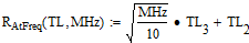
TL3 = series resistance per meter, 10 MHz
TL4 = shunt conductance per meter, DC
TL5 = shunt conductance per meter, 10 MHz
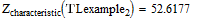
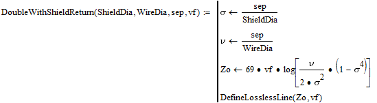
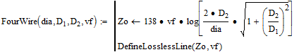
Zo is the characteristic impedance.
vf is the velocity factor. See note 1.
RsDC is the series resistance per meter at D.C.
Rs10MHz is the series resistance per meter at 10 MHz.
Gp10MHz is the parallel conductance per meter at 10 MHz.
To get lines that have no variation with frequency ("flat" lines), specify 10 MHz values that are the same as the D.C. values.
Zo is the characteristic impedance.
vf is the velocity factor. See note 1.
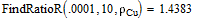
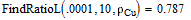
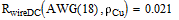
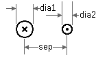
r is the wire conductivity. Usually rCu is specified here.
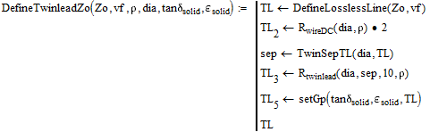
dia is the wire diameter, in meters.
A 10 MHz resistance will be computed that is accurate when the wires are widely separated. (Hint: Atlc2 will tell you the 10 MHz resistance.)
See note 2.
Note: The solving functions assume the resistance changes with the square-root of the frequency. But for close spaced twinlead, the true power can be closer to .54 than .50. If your band is far from 10 MHz then the error can be large. You might have to adjust TL3 or r to get the correct resistance for your band. Rtwinlead will tell you what the resistance should be. The actual resistance the program will use is:
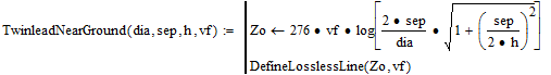
vf is the velocity factor. See note 1.
r is the wire conductivity. Usually rCu is specified here.
dia is the wire diameter, in meters.
sep is the wire separation, in meters.
A 10 MHz resistance will be computed that is accurate when the wires are widely separated. (Hint: Atlc2 will tell you the 10 MHz resistance.)
See note 2.
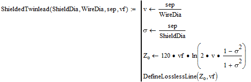
Zo is the characteristic impedance.
vf is the velocity factor. See note 1.
rcc is the resistivity of the center conductor. Usually rCu is specified here.
diacc is the diameter of the center conductor, in meters.
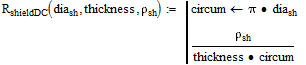
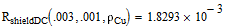
rsh is the resistivity of the shield conductor. rCu and rAl are common.
thsh is the thickness of the shield conductor, in meters.
See note 2.
vf is the velocity factor. See note 1.
rcc is the resistivity of the center conductor.
diacc is the diameter of the center conductor, in meters.
rsh is the resistivity of the shield conductor.
diash is the inner diameter of the shield conductor, in meters.
thsh is the thickness of the shield conductor, in meters.
See note 2.
MHz should be roughly the band where the line will be used.
Set vf = 1 when the dielectric is all air. Set vf = 0.66 when the dielectric is solid polyethylene. When the dielectric is non-uniform, an average dielectric constant is assumed from the velocity factor you provide.
Note 2: tandsolid and esolid are for a solid block of the dielectric material, even if the transmission line has foam. The velocity factor will be used to determine how much air is present in the dielectric, and the dielectric loss will be adjusted accordingly. This formula works for any dielectric-air mixture. esolid is a relative value (a number close to 1). (If vf=1 then the numbers you provide for tandsolid and esolid are effectively ignored.)
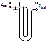
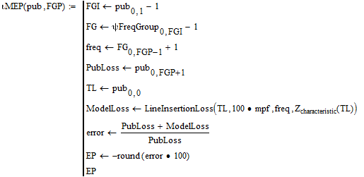
The choice between "Input" and "Output" functions should be made based on which current direction convention more closely matches your analysis, not on which way the power is moving. All equations allow power to be moving in both directions and either box could be a generator.
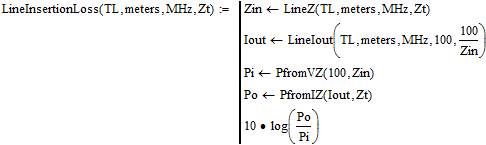
This is the power lost in the line due to dissipation. The lost power is converted into heat. For lossless lines, this function will always give a zero result.
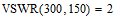
Example: Suppose a receiving antenna has a gain of 12 dB and a terminal impedance of 150 ohms. If the antenna is connected to a 300-ohm transmission line, what is the net gain?
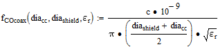
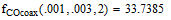
This is the frequency where a TEM and TE11 mix begins, making the cable useless. fCOcoax is in GHz. er is for the dielectric. mr is assumed to be 1.
In the following :
FG = frequency group number.
LN = loss in dB/100ft at freq fN.
Rcc = DC resistance of center
conductor per 100ft.
Rsh = DC resistance of shield
per 100ft.
EN = model error in percent at
frequency fN.
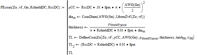
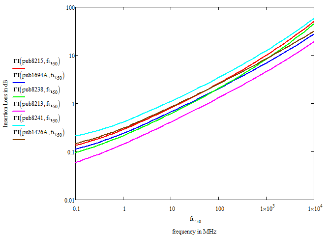
For each cable type above, PEcoax determined a shield thickness that would make the shield DC resistance match the shield DC resistance given on the manufacturer's web site. The DC series resistance TL2 was set to match the sum of the shield and center conductor resistances given by the manufacturer. The center conductor conductivity rCC was computed from the gauge number and the DC resistance.
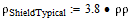
The predicted losses match the published losses better when tandPE is increased to 0.00064 and when the shield conductivity rShieldTypical is 3.8. These were determined experimentally. The justification for them is not known.
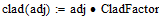
The general model does not work well with copper clad conductors. The clad function was used to reduce the DC resistance, which makes the model more accurate above 1 MHz but less so below. If you are using a clad cable below 3 MHz, you might want to reduce the CladFactor value some.
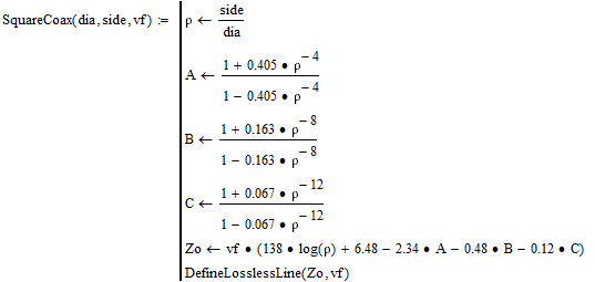
All of the following are taken from Reference Data For Radio Engineers, Howard W. Sams & Co. 1977. All are lossless, with the series resistance and shunt conductance set to zero. Rs and Gp can be overridden with direct assignments to TL2, TL3, TL4, and TL5 after the lines have been created.
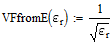
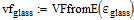
If the line fields are fully imbedded in a uniform dielectric, set vf = VFfromE(er) where er is the relative dielectric constant.
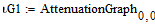
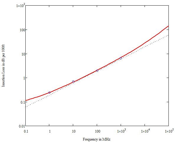
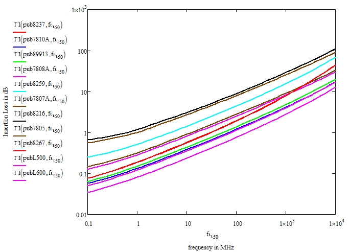
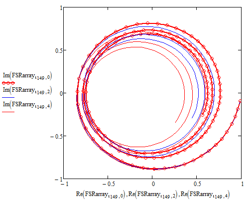
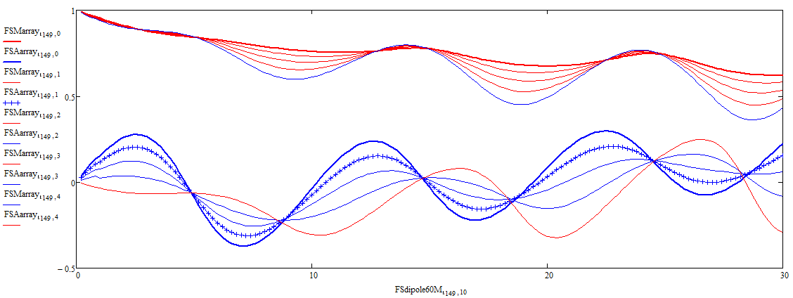
You specify which coax is to be graphed by setting the AttenuationGraph variable. The red line is the loss the model predicts. The blue circles are four points taken from the manufacturer's nominal loss data.
The dotted line is the model but with its dielectric loss and DC resistance set to zero. For most cable types, the graph will show that the DC resistance dominates below 1 MHz, and the dielectric loss dominates above 1 GHz.
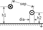
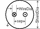
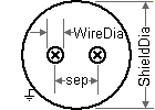
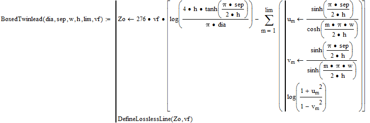
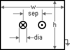
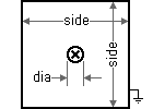
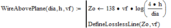
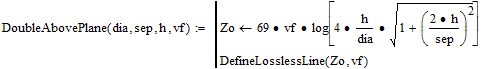
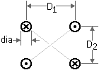
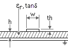
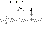
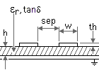
The twinlead must be centered in the box.
This is accurate if:
dia << sep
dia << w
dia << h
lim = infinity
See if this works: Set lim to a low value, then raise it until the result converges.
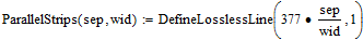
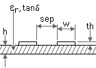
This is a rough approximate formula, accurate if:
wid/sep > 10.
Do not use this formula when the strips are separated by a PC board.
The atlc2 program (arbitrary transmission line calculator) can be used to find the parameters for any geometry. You just draw a cross-section of the transmission line, and it will tell you the characteristic impedance, velocity factor, and series resistance. Arbitrary dielectric configurations are allowed. Atlc2 can be found at www.hdtvprimer.com/KQ6QV/HomePage.html .
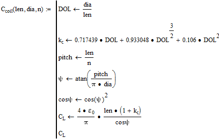
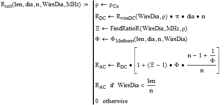
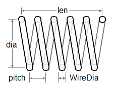
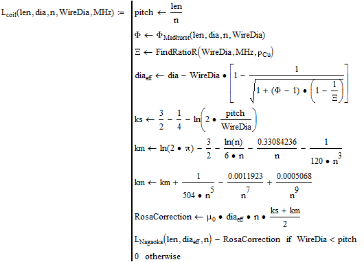
These are for single-layer copper coils in free space.
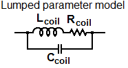
The functions support the lumped parameter model.
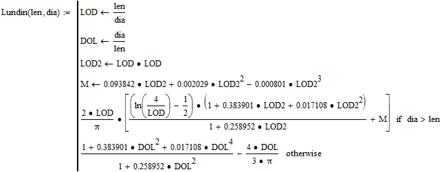
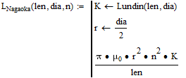
Lundin's formula for calculating Nagaoka's coefficient (see http://www.g3ynh.info/zdocs/magnetics/part_1.html) :
len and dia are in meters, n is the number of turns.
Ccoil is the apparent terminal capacitance for the lumped parameter model at low frequency. (See DAE formula 5.3 on
www.g3ynh.info/zdocs/magnetics/appendix/self-res.html .)
This capacitance can be very misleading. Common misconceptions:
1. This is mostly the capacitance between adjacent turns.
2. The capacitance is responsible for the coil's principal self-resonance.
In fact, the self-resonance comes from the wire of the coil acting like a transmission line, and the apparent capacitance changes substantially as the frequency approaches self-resonance.
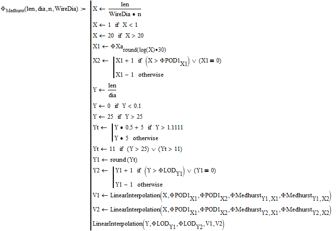
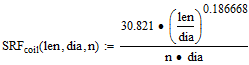
len, dia, and WireDia are in meters, n is the number of turns. The accuracy of the formula is better than 3%. (See the last formula on http://www.g3ynh.info/zdocs/magnetics/part_2.html)
FF < 0.5 has the highest Q
FF = 1.5 has highest self resonance
FF > 2 has the least core volume
FF > 2 is easiest to shield
FF > 2 has the highest breakdown voltage
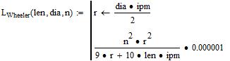
The Wheeler and Esnault-Pelterie formulas are usually written for inches, but here they have been modified to use meters, consistent with the rest of this document.
len, dia, and WireDia are in meters, n is the number of turns. This formula is accurate to better than 1% until the frequency approaches self-resonance. (See www.g3ynh.info/zdocs/magnetics/part_1.html. See Stroobandt formula at hamwaves.com/antennas/inductance.html.)
MHz is the frequency. L changes very little with frequency, so just a rough approximation is required here.
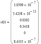
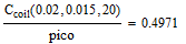
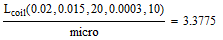
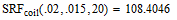
for len=.02, dia=.015, n=20, WireDia=.0003, MHz=10
hamwaves.com/antennas/inductance.html says:
L=3.3741 mH
R=1.05587 W
C=.3201 pF
SRF=115.5 MHz
Q=200.79
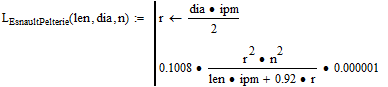
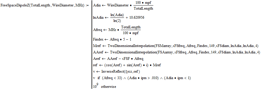
Terminal impedance symmetric straight uninsulated copper dipole 100 feet long in free space as determined by NEC-4 (83 segments)
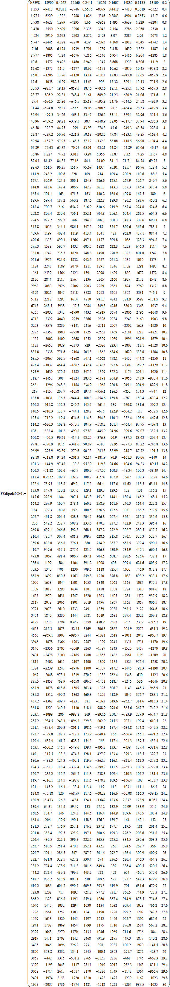
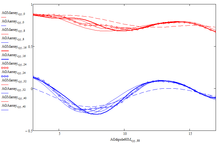
Terminal impedance of horizontal symmetric straight uninsulated AWG #12 copper dipole 100 feet long at various heights as determined by NEC-4 (83 segments)
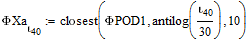
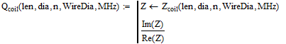
SRFcoil is the frequency in MHz of the coil's principal self-resonance, accurate to around 10%. (If the coil wire has insulation giving the wire a velocity factor of 0.9 then the self resonance would be roughly 0.9*SRFcoil.)
The purpose of this function is to tell you if you should believe the other functions. For operating frequencies less than 40% of SRF, the functions are as accurate as stated. For 40% to 70% the functions are useful but somewhat off. Above 70% you are probably making a mistake.
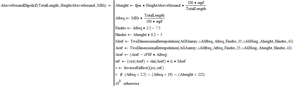
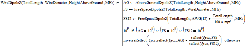
TotalLength and WireDiameter are in meters. This function is intended for use from 1 MHz to 30 MHz. The data comes from a NEC-4 simulation of a 100-foot dipole (resonant at 5 MHz). The farther you stray from that, the less accurate the result will be, but the function is thought to be very accurate for all HF dipoles. The function returns a 109 impedance if any input is outside the range that gets accurate results.
TotalLength and HeightAboveGround are in meters. This function is intended for use from 1 MHz to 30 MHz. The data comes from a NEC-4 simulation of a 100-foot dipole (resonant at 5 MHz) at heights between 5 and 220 feet. The dipole is AWG #12 copper, uninsulated, straight, level with the ground, and center-fed. The farther you stray from these, the less accurate the result will be, but the function is thought to be very accurate (assuming NEC-4 is accurate) for all such HF dipoles in the range l/50 < height < 1.14l. Above that, use the free space function. The function returns a 109 impedance if any input is outside the range that gets accurate results.