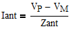
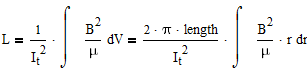
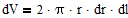
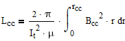
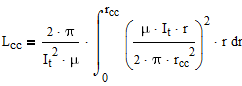
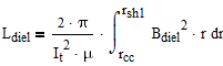
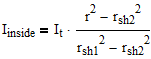
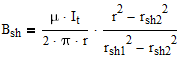
where  is the field produced by current
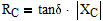
  , the total current in the center conductor. The integration is over all space containing the field.
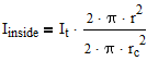
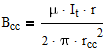
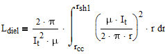
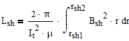
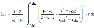
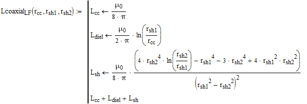
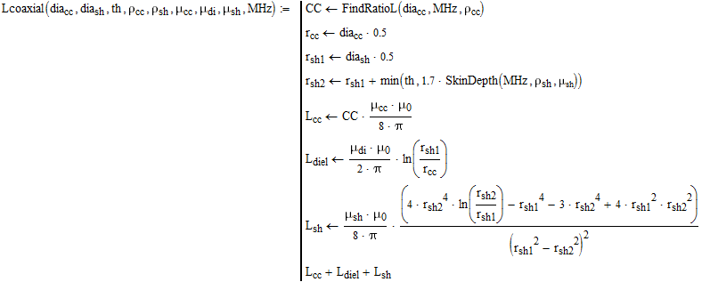
The integration can be divided into 3 regions: center conductor, dielectric, and shield.
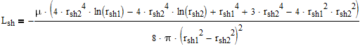
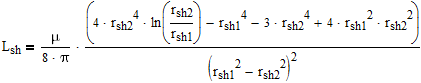
For a length of 1 meter and a frequency approaching 0 :
Fs is a constant. Atlc2 can be used to show that this constant is about 1.7 for typical coaxial cable.
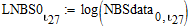
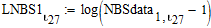
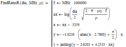
Resistance and Inductance ratios for solid round wires, published by the National Bureau of Standards, now NIST:
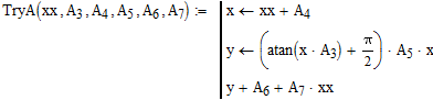
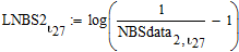
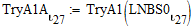
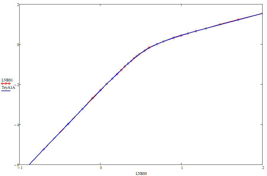
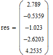
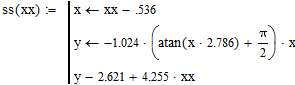
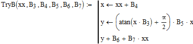
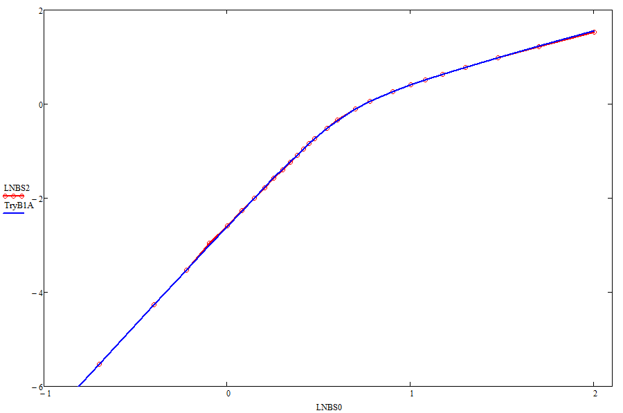
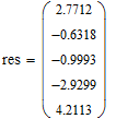
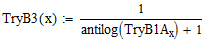
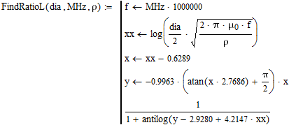
This is a curve-fitting exercise.  is a proposed function for predicting the NBS resistance data. Find the constants
  -
-  that will give the most accurate fit.
This data is used in determining the A.C. resistance and inductance of coaxial cable. It is not accurate for twinlead.
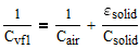
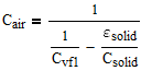
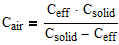
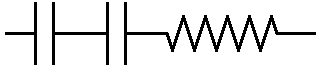
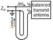
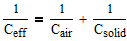
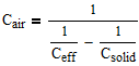
(You can imagine all of the air squished out of the foam, so that there is solid dielectric against one conductor and all the air against the other. Then an imaginary third plate can be added where the solid and the air meet. If the third plate follows an equipotential surface then the device will work exactly as an unmodified device, and is obviously two capacitors in series.)
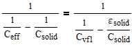
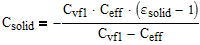
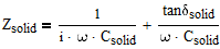
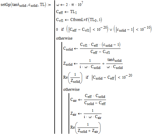
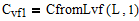
For a second equation, if the solid were replaced with air then the velocity factor would be 1, and the net capacitance could be found from the inductance :
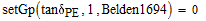
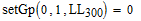
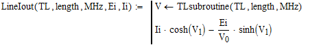
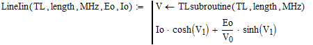
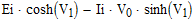
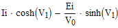
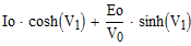
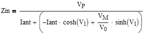
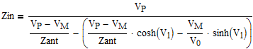
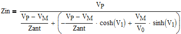
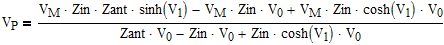
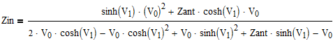
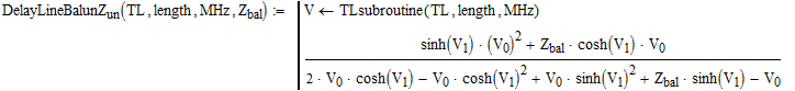
The result is derived twice, once using output functions, and once using input functions. The same result should be obtained either way.


 )
)