2/6/09
How big
should the antenna be?
Will an indoor
antenna work?
Since
building materials absorb and scatter RF unpredictably, there is no way to
compute whether an indoor antenna will work.
The maximum range for indoor antennas is usually somewhere between 10
and 20 miles from the tower, depending on the terrain and the local
obstacles. Being able to see the
transmitting antenna can extend this to 30 miles. These numbers assume full-power stations.
With
an indoor antenna, dropouts may occur as people move around the room. An indoor antenna might not be high enough to
be above outdoor bushes and trees, which could result in dropouts when the wind
blows.
How many stations
can I receive?
The bigger your antenna is, the higher its gain will be, and thus the greater the distance it will cover. But high gain antennas are very directional, which may force you to re-aim the antenna when you change channels. If your most difficult stations were ones that you don’t often watch, then a high gain antenna would be more of a burden than a boon. You might have to do a considerable amount of experimentation to figure out how to receive some weak stations. You need to make a very pragmatic decision about what stations you want to receive. It is natural to want every receivable station. But that might be unwise.
The following sections will show how to estimate the antenna necessary for one station. You have to repeat that computation for each station that you are considering.
www.antennaweb.org
This site is your starting point. You tell it your address and it will tell you what kind of antenna you need. The site will give you a list of your stations and a compass heading to each. Unfortunately it is not as accurate as you may need:
- It doesn’t know about your local
obstructions.
- It doesn’t admit that typical
antennas are often much better on some channels than other channels.
1. Start by going to www.antennaweb.org and clicking on “Choose an antenna”.
2. Fill in your complete address and click “submit”. (Ignore the questions about obstructions and house type.)
3. Click on “View street level map”.
4. If the map is not centered exactly on your house, place the cursor where your house is and click it. Both the map and the chart will be updated.
5. You can close the map and select “Show Digital Stations Only”.
The chart shows your stations ranked from easiest to hardest. The color code estimates the gain your antenna must have, as follows:
VHF Low (2-6): VHF High (7-13): UHF:
-25 dBd -15 dBd -10 dBd (yellow)
-12 dBd -9 dBd -6 dBd (dark
green)
-2.5 dBd -2.5 dBd -2.5 dBd (light
green)
-2.5 dBd 0 dBd 0 dBd (red)
-2.5 dBd 0 dBd 0 dBd (blue)
4 dBd 6 dBd 8 dBd (violet)
4 dBd 6 dBd 8 dBd (pink)
You might be able to get additional channels, but they will be difficult and might require “heroic measures”, such as the 16-bay antenna described on a later page. To find out what those channels might be, go back to the map and click on a different house, one situated a little better than yours. Such a house would be one in a high spot with a clear view for a long distance in the direction of the station. (If you are in a flat region, select a spot 10% closer to the transmitter.)
Correcting for
local obstructions
Obstructions
requiring corrections are:
·
Buildings
– It is best to assume neighboring structures block all signals.
·
Trees
-
§ UHF It
is best to assume that trees block all signals.
§ VHF-high A correction of 6 dB is adequate. Add this to the required antenna gain.
§ VHF-low A correction of 3 dB is adequate. Add this to the required antenna gain.
·
Embankments
and small hills – These block all signals.
·
Hills
- Antennaweb has already corrected for significant hills. But if you pointed antennaweb to a house
that, unlike yours, has no hill in the way then you must now correct for your
hill.
When
obstructions block all signals then you will be relying on diffraction around
the obstacles. Go to the spot where the
antenna will be.
- If no local obstacles block your
view of the far skyline then: If
the signal coming from the skyline skims over the tops of some close-by
obstructions then add 3 dB per obstruction to the required antenna gain,
otherwise there is no correction.
- If your view of the distant
skyline is blocked by obstacles then you must determine the diffraction
penalty by the procedure which follows :
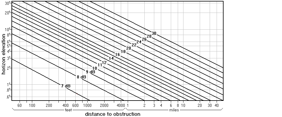
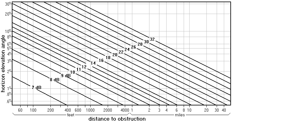
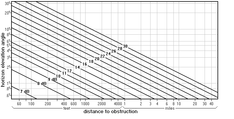
From
about where the antenna will go, find the elevation angle to the top of the
obstruction in the exact direction of the station. (You might need a carpenter’s level to find a
point in the distance that would be 0° elevation. Then if you hold up a ruler vertically 12
inches from your eye, each inch on the ruler would be 4.8°.)
Next
determine the distance from your antenna to the base of that obstruction.
Finally,
apply both numbers to the correct graph below to find the diffraction penalty
in dB. Add this number to the required
antenna gain.
Diffraction
penalty for channels 2 to 6:

Diffraction penalty for channels 7-13:

Diffraction
penalty for channels 14-69:

This
penalty is also called “knife edge diffraction”.
An improved
computation
As
the following diagram shows, the correct diffraction angle is not a, but
rather a-b.

So
your computation is more accurate if you can figure out the value of b.
Multiple
obstructions

If
there is a second obstacle then compute two diffraction penalties, one using
angle a-b and one using angle b-c. This can be extended to 3 or more
obstructions. When the obstacles are
close together, they behave more like a single obstruction.
Multi-path problems
Before
spending money on an antenna, you need to know if you have multi-path
problems. For each DTV station you want,
find the analog station that is closest in frequency and in the same direction. Tune in that station. (Borrow a set of rabbit ears if
necessary.) Ignore the snow. You are looking for ghosts. They are caused by the signal arriving by
more than one path. Diffractions around
hills and reflections off of buildings are the usual cause. Normally they are too dim to see. But if the direct path to the transmitter is
blocked, the ghosts will be very strong.
If the ghosts are arriving from the rear then you need an antenna with
no reception to the rear. But most
ghosts come from the front or the side.
A very high-gain antenna will have a very narrow beam. Such an antenna can receive the strongest
signal and mostly ignore signals from other directions.
Sometimes
there is only one strong ghost. In this
case an antenna with a null out the side or the front can be used. (What this means will be made clear in pages
which follow.) Your strategy is to
rotate the antenna until the ghost direction coincides with the null. Hopefully killing the strongest ghost will
allow your receiver to lock on to the DTV signal. Since the antenna is no longer pointed
directly at the station, it needs extra gain.
This aiming is so critical that a rotor is often impractical. In that case you might need separate antennas
for each station.
Another class of multi-path was described in the preceding page: two signals from the front with no delay. Although the phenomenon is the same, no ghost is visible. You have this problem if moving the antenna a few feet, left or right (and maybe up or down), causes a big change in signal strength. This also requires a higher gain antenna. Unfortunately this problem is usually not discovered until after the antenna is purchased.
Additional
corrections
Starting with the sum you computed
above:
- Add 2 dB (VHF) or 4 dB (UHF) if
you will be mounting it in the attic.
- Add about 6 dB if you have
multi-path problems.
Due
to differences in receivers, neighborhood electrical noise, misinformation on
web sites, the weather, and other intangibles the computation you made is
probably not more accurate than ±4 dB.
So you might consider adding in another 4 dB to insure that the first
antenna you buy is the only antenna you buy.
Now, finally, you can select an antenna. The pages that follow explain how much gain you can expect from several common antennas.
A Combo versus a
UHF-only antenna
In 2009 the FCC will give each station
the choice of staying in UHF or moving to VHF if that is possible. Each band has advantages and
disadvantages. The opinion of this
author is that VHF-high is the best band for DTV, given that VHF-low is plagued
by appliance noise problems and UHF is plagued by tree and hill problems. The FCC document DTV
Tentative Channel Designations tells where your
stations will be after 2009. You should
take that into account for this decision.
You must choose between a combo (an antenna that works for both VHF and UHF) and a UHF-only antenna. The best UHF-only antennas are much stronger than the UHF part of any combo antenna. If antennaweb.org shows that any of your “must have” stations is in the purple range (most difficult) then this author recommends you get a Channel Master 4228 (a UHF-only type) and a 7777 preamplifier. That means you might have another antenna project in 2009. But it is at least as great a waste of your time and money if your first try is an antenna that is too weak. Only a couple dozen stations nationwide are choosing to remain in channels 2-6 after 2009, so putting a channel 7-13 Yagi on the mast with the UHF-only antenna is a good strategy for many people.
Related topics
FCC database, accessing (How to find out a station’s power and other info.)
This page is part of “An HDTV Primer”, which
starts at www.hdtvprimer.com