7/8/06
Merging feedlines
How to combine
antennas that point in different directions
There
isnít a simple ideal solution to this problem.†
To find your best compromise you need a little more knowledge than you
probably want.
If your lack of technical background makes difficult
understanding the details of what follows then just skim over them and donít
worry about it.
The common splitter
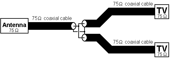
A common splitter will also serve as a combiner.† (Sometimes a distinction is made.† A splitter doesnít have to be a low loss device since it normally comes after the preamplifier.† But in fact most splitters perform about as well as good combiners.)† But what a splitter does is a bit subtle.† Suppose you simply make a Y-connection between the feedlines:

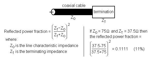
A law of physics: If a transmission line terminates with a load not equal to the lineís characteristic impedance, there will be reflections.† In the above diagram, the first segment ends in two loads of 75 ohms in parallel, which would be 37.5 ohms.† The amount of reflected power is found from the formula:

Signals can literally bounce back and forth inside transmission lines.† In the above case, 11% of the antenna power is reflected at the Y-connection.† The reflected power is mainly retransmitted.† So the job of a common splitter is to divide the power without causing reflections.
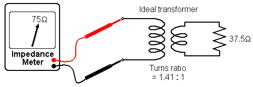
An ideal transformer will fix this.† The impedance change equals the square of the turns ratio:

So the following splitter will divide the power without causing reflections:

Unfortunately it is not possible to construct transformers for VHF or UHF that are even close to ideal.† (There are always too many unintended resistances and capacitances.)† So splitters donít contain transformers.† What they actually contain varies from maker to maker.† But if they are well made, they will behave the same as the theoretical splitter described above.
Each TV gets half the power, which is equivalent to a 3 dB drop in signal level.† Most splitters are about 90% efficient.† The other 10% is either converted into heat in the copper and ferrites or lost to reflections.† So the actual loss at the splitter is closer to 3.5 dB.
The splitter used as a combiner
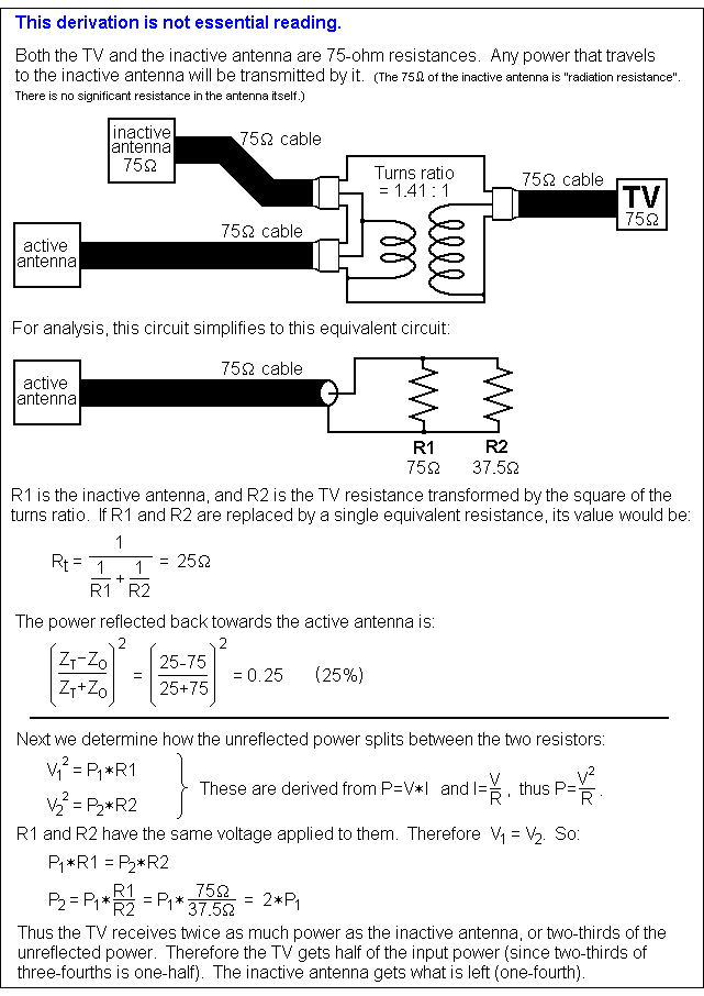
When a splitter is used as a combiner, reflections are unavoidable:

In summary, when a 2-way splitter is used as a combiner,
1. one quarter of the input power is reflected back towards the input,
2. one quarter of the input power is diverted to the other input, and
3. one half of the input power is forwarded to the intended load.
These numbers assume the splitter is 100% efficient.
It might seem worthwhile to search for a combiner circuit that will not cause reflections.† But no such circuit exists.† An ideal splitter works as well as any combiner ever devised.
Only 50% of the input power is forwarded to the load.† This is equal to a 3 dB loss.† If the device is 90% efficient then a 3.5 dB loss is expected, the same as the loss seen when the device is used as a splitter.
(It will be explained later that when the two antennas are pointed at the same TV station, the reflected currents subtract to zero, and as if by magic, the 3 dB combiner loss turns into a 3 dB gain.)
When the antennas point in different directions, the cable lengths are not critical in any way.
Ways to avoid the 3 dB combiner loss
1. Use a rotor.† This avoids the combiner altogether.† But rotors are especially annoying for DTV stations.† Most people who have them donít like them.† Worse still, DVR units (such as TiVo) canít make rotor adjustments.† After you have missed recording a few programs you will wish you had two antennas.† Some DVRs can record two programs at once, which the rotor makes impossible if the two stations are in different directions.
2. Use a switch.† This author especially likes the Radio Shack 15-1968 switch, which comes with an infrared remote control.† But this solution has the same DVR problems as the rotor.
3. Use a diplexer.† This is a frequency-selective combiner.† (It looks like a splitter.)† Two types are commonly available.† The first is a VHF/UHF splitter/combiner, which will have only the 0.5 dB efficiency loss.† If your stations in one direction are all VHF, and the stations in the other direction are all UHF, then this device is perfect for you.† The second is the Channel Master Join-tenna.† (See Join-tenna.)† This device is ideal if one of your directions has only one station.† Unfortunately both of these solutions are inapplicable for most people.
4. Put amplifiers ahead of the combiner?† Many people have tried this.† It doesnít work.† It does make the combiner loss irrelevant.† But having two amplifiers doubles the amount of noise presented to the TV.† The resulting 3 dB drop in the signal-to-noise ratio is the same as you would see if the amplification came later.† (The 0.5 dB efficiency loss is eliminated, which is a real improvement.)
Other splitters
When a good N-way symmetric, lossless splitter is used as a combiner:

Related topics
Join-tenna† (a device for combining antennas)
Rotors† (motorized antenna pointing)
Splitters/combiners/diplexers† (What do they do?)
75-ohm
terminators† (Are these necessary?)
Impedance† (What is this?)
Mismatch† (Does this matter?)
This page is part of ďAn HDTV PrimerĒ, which starts at††† www.hdtvprimer.com