12/29/10
Temporary page
Eventually this information will be revised
for presentation in the style common for the Primer.
The bad news is that the
new 4228HD and DB-8 are both wrecks. I
haven’t yet found any good news.
4228 Gain:
A old Channel Master 4228
B Raw gain of 4228HD (new) with harness and balun removed
C 4228HD as delivered (as manufactured by Channel
Master)
D 4228HD with feed point bent (pushed rearward) away from
dipoles
E 4228HD with improved harness (and with the Channel Master 4:1
balun that came with the antenna)
F 4228HD with improved harness and simple 4:1 balun
G 4228HD with improved harness and simple 2.5:1 balun
All of these except plot B
are net gains (the raw gain minus the coupling loss). B is like the total raw gain of two 4-bays
placed sided by side. The goal of the
feed system is a net gain as close to B as possible.
Channel Master 4228HD
This is developed from the
4221HD, which is an excellent 4-bay. But
the 4228HD engineer was some clown who knows a lot less about antennas than he
thinks he does. The “phasing harness” is
awful. It looks like it was designed by
a plumber. It is so close to the dipoles
that it can touch them if anything is slightly bent. The balun box tends to sit almost in the
plane of the dipoles. If you just push
it back so that it is two inches behind the dipoles, the gain improves by about
1 dB (plot D above). You will have to
tie it into that position, perhaps with a tie-wrap around the mast.
Plot E show the gain with
a redesigned feed harness. This harness
more closely resembles an ideal twinlead transmission line. The huge gap between plots C and E shows how
badly they bungled the feed harness.
Plot F replaces the
Channel Master balun with a simple 4:1 balun made from
150-ohm quarter-wave segments, an idealized version of the Channel Master
balun. Plot F roughly matches plot E,
indicating that the Channel Master balun is reasonably
efficient.
Plot G uses a 2.5:1 balun
made from two 120-ohm quarter-wave segments.
The improvement is considerable.
This is no surprise. A 4228 is essentially
two 300-ohm antennas connected in parallel, which would be 150 ohms. One would guess that the 4228 requires a
150-ohm to 75-ohm transformer, also called a 2:1 balun.
As delivered, the 4228HD
outperforms a 4-bay by only a very small amount, which is pretty sad. The main problem is that each half of the
harness is made of two wires of different lengths. Part of the longer one is un-cancelled and
thus radiates. Although this seems like a
small and inconsequential segment, keep in mind that it carries four times the
current of the other dipoles and thus radiates four times as effectively. The harness radiation disrupts the radiation
pattern of the other eight dipoles, lowering the raw gain of the antenna.
(Some of
the above plots have dips at channels 23, 30, and 60. These are caused by resonances in the loops
of the reflector. Also there are
resonances at channel 47 and 39 caused by vertical currents that include the
mast and which disappear if the mast is an insulator. Some of these resonances are excited by the
feed harness and are made worse by pushing the feed harness back towards the
screen. If Channel Master knew about
these, it might explain why they put the harness so close to the dipoles. But the correct fix is to make the harness
out of closely spaced, smaller gauge wires.)
In theory, fixing the
4228HD is not hard: You just replace the
phasing harness with two 4:1 baluns and a 2:1 combiner. A nut-driver is the only tool you need. If the loss in the baluns and combiner is 0.5
dB then the performance will be 0.5 dB less than plot B. Unfortunately finding low-loss devices seems
to be impossible. Such devices are becoming common, but
they are not yet sold as free-standing units.
Until I think of something
better, if you want an 8-bay, you should probably buy two Channel Master 4-bays
instead. I believe that antenna comes
with a low-loss balun, 0.2 dB or better.
(Tom, at http://www.antennahacks.com
has tested splitters, and the Perfect Vision PV22-233 was the best he found,
averaging a roughly 0.5 dB loss (0.5 dB beyond what is expected for an ideal
device). I have not tested
it. I suspect it is also sold under
other names.)
VHF gain:
A old Channel Master 4228 net gain, balun loss not included
B 4228HD (new, as delivered) net gain
C 4228HD raw gain
D 4228HD net gain with the four screen mounts replaced by insulators
E Rabbit ears, 40” 45º, net gain
Plot A is without a
balun. A typical ferrite transformer
balun has a loss of 0.5 to 1.0 dB for these frequencies.
Comparing Plot B to C
shows that the UHF balun is causing about a 3 dB loss at VHF. In effect the antenna is direct-connected to
the 75-ohm cable with no impedance matching.
Also, the lack of a proper VHF balun means there could be additional
losses due to radiation from the coaxial shield.
In plot D, the four 4-inch mounts that connect the radiator assembly to the screen are replaced by insulating bars. (Insulating washers would not be good enough. At 200 MHz their capacitance is almost a direct connection. It is best if the whole 4-inch rod is replaced with plastic.)
I had High hopes for this
antenna for VHF. I figured that with
fewer vertical wires, it would not have the vertical currents of its
predecessor. But the vertical rods it
retains are enough to cause trouble.
The dip at channel 7 is
caused by the antenna radiating greatly straight up and down, which diminishes
its forward gain.
The dip at channel 9 is
caused by the antenna radiating more out the back than out the front, which
diminishes its forward gain. (The
harness and dipoles induce a high current in the vertical front ½” support bar,
which travels to the screen where it goes to the top and bottom and then turns
horizontal. One complete path runs from
the upper left corner to the bottom left corner. The other path, in the right side, has the opposite
phase. Each path is about 1 wavelength,
so there is a current null at the middle of each vertical bar where the current
reverses direction. At channel 9 the
path is slightly less than a wavelength, and so the screen acts as a
director. In plot D, this path is cut,
eliminating the dip.)
(The dip
in channel 7 starts with a current null coinciding with the feedpoint
in the shorter harness wire. For channel
11, it is the longer wire. The null
blocks the current but doesn’t stop it from flowing in from the opposite side
of the antenna. The result is a
massively unbalanced current flow in the harness. That unbalanced current in the vertical feed
bus induces a large current in the vertical front ½” support bars. This current flows into the screen,
disrupting the currents there.)
All of these problems
would be eliminated by a symmetric feed and an insulated screen.
NEC simulation programs
are usually a little off. Although the
graph shows dips in channels 7 and 9, the graph is not
trustworthy as to how close the dips are to channels 8 and 10.
To use this antenna for
VHF, I recommend replacing the feed harness with two baluns and a splitter.
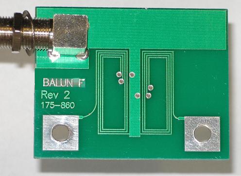
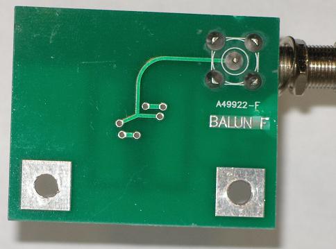
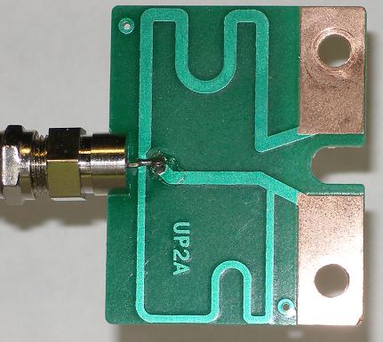
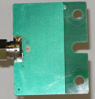
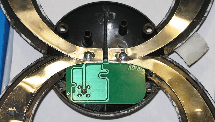
The 4228HD
balun
The balun is in a black
box that is glued shut.
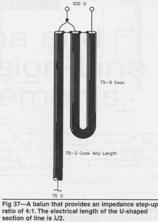
The above diagram comes
from the ARRL Handbook. The 4228 balun
is roughly the same. Some differences
are:
1.
In theory, if the two twinlead lines are long then this balun has
a very wide bandwidth. But if they are
only a quarter-wave long then they have less bandwidth but are quarter-wave
transformers that can match anything to anything. If the quarter-wave segments have a
characteristic impedance of 150 ohms then this is a 4:1 balun. If they are 106 ohms then it is a 2:1 balun. (To match Z1 to Z2, the
quarter-wave segment must be sqrt(Z1*Z2).)
2. The 4228 balun segments
are a quarter-wave long for UHF. The two
coil structures are not magnetically linked significantly. When I first saw this circuit I assumed it
was a 2:1 balun, which would be a good match for the 4228.
3. According to the ATLC
program, the circuit board trace is 129 ohms, 0.62 velocity factor. (A 3:1 balun?)
4. Apart from being a
quarter-wave transformer, each coil is also a step-up transformer with a Vout/Vin of roughly 1.2.
Considering these two effects together, this is clearly a 4:1
balun. A NEC-4 simulation verified this.
5. The two segments are not
equal in length: One is 12% longer than
the other. I cannot figure out why they
did this. Generally, asymmetries are
always bad in antennas. If anybody has
additional insight into this balun, I would like to hear from him. Email me at kq6qv@aol.com.
With slightly different
artwork this could have been a 2:1 balun, and the antenna would have worked
better. This is a UHF balun. For VHF it will pass the signal but will not
properly transform the impedance or block unbalanced currents.
A properly
designed 8-Bay
I have taken a stab at
redesigning the 4228. Any antenna twice
as big should be 3 dB better. Anything
less than 2.5 dB is bad engineering. The
feed harness is a transmission line and follows rules that every electrical
engineer is supposed to know. If you
depart from ideal, you must determine what you are giving up.
This try disregards the
VHF performance. Someday I hope to take
another look at this for VHF.
The feed harness will
serve as an impedance transformer. Two
lossless types are common: A
quarter-wave segment, and a half wave tapered
segment. I chose the quarter-wave
segment since it can match extreme impedances without itself ever having to be
those impedances. I divided each
harness-half into two 5-inch transformers.
I simulated the antenna with the harness missing, then
used Mathcad to search for the best impedances for the transformers. The 4-bay seems to average about 425 ohms. A 316-ohm quarter-wave will transform that to
235 ohms, and a 188-ohm quarter-wave will transform that to 150 ohms. The two 150-ohm halves in parallel make 75
ohms, which needs a 1:1 balun. Such
baluns can be lossless and very wideband.
Transforming to 300 ohms also works.
The 300-ohm version seems slightly lossier,
even before adding in the 4:1 balun loss.
The harness geometry:
The length of the B
segment is 6” plus whatever wraps around the standoff screw terminal. Both wires of each B segment must be exactly
the same length. Each of the four
standoffs is a 1.75” F/F threaded ¼” hex or round aluminum spacer. I recommend 0.1-inch diameter aluminum
wire. Such wire is not stiff enough to
support itself, so a few plastic spacers will be necessary to maintain the
required wire spacing. (Warning: Too much plastic will change the velocity
factor. Using larger gauge wire would
require a larger spacing, increasing crosstalk with both the screen and the
dipoles. Building the feed harness out
of commercially available 300-ohm twinlead does not work because of the
velocity factor. I looked for a good compromise based on that but did not
find one.)
Plot D shows the expected
net gain:
(I have never actually built this antenna, so
I have no photos of it. Antennas are
mathematical devices, and any proposed design must first work mathematically.
This modification is a little difficult, just
tricky enough that I am leery of encouraging anybody to try it. The few details on this page are just enough
for an engineer to work from, but someone less serious should probably avoid
this project.
I had two reasons for creating and publishing
this proposal: First, to encourage
manufacturers to move in the right direction, and second, so that buyers would
recognize a good 8-bay should one ever appear on the market.)
Tom Ballister has
constructed this modification. He has
good test equipment for measuring the results.
His efforts are described at http://www.antennahacks.com/AntennaHacks.htm . He reports that the improvement over the
unmodified antenna is very significant at UHF, but the VHF performance is worse
below channel 10. I hope someday to look
into fixing its VHF performance. –Ken 12/29/10
AntennasDirect DB-8
All the 8-bay makers seem to
be copying each other’s mistakes. The
DB-8 has some of the same harness errors as the 4228HD. Replacing the harness with two baluns and a
combiner would make it the same as the old DB-8. But the DB-8 is not fixable. The DB-8 dipole elements are only 6.2 inches
long, compared to 8.0 inches for the 4228.
This biases the DB-8 toward the higher channels. The DB-8 was always a bit weak below channel
40. Now that channels above 51 are gone,
it is no longer a reasonable antenna, even with the harness fixed. Some day AntennasDirect will figure out that
they have to rescale this antenna.
The DB8
balun
The diagram comes from the
ARRL Antenna Book. The DB8 balun is the same
except the U-section has been divided into two quarter-wave transformers having
characteristic impedances of 54 and 75 ohms, velocity factor 0.60. It will match 200 ohms with 75 ohms, making
it a 2.66:1 balun.
This balun is a good
impedance transformer but not a very good balun. A balun is supposed to block unbalanced
currents. This one creates them. Also it does not prevent radiation from the
coaxial shield. A balun of the 4228HD
general type would have been a little better.
This balun will mostly
filter out VHF, so don’t even think of using this antenna for VHF.
Some new
simulations: net gain
A old 4228, not including balun loss
B new 4228
C old DB8, not including balun and combiner losses
D new DB8
E ClearStream 2
F ClearStream 4
G Winegard HD-7698P, not including balun loss
H AntennaCraft HBU44, not including
balun loss
I DB2, not including balun loss
J Channel Master 2020
A Rabbit ears, 40” 45º
G Winegard HD-7698P, not including balun loss
H AntennaCraft HBU44, not including
balun loss
J Channel Master 2020
Winegard
HD-7698P
The Winegard literature is
correct: The antenna is for channels 7-69.
So this antenna will be obsolete on June 12. In every other respect this seems like a good
antenna. But throwing away 2 dB for a
short-lived market advantage seems silly to me.
The antenna has a
combiner/balun that employs a ferrite transformer balun. Just from looking at it I would say it might
be especially low loss for a transformer balun.
But presently I have no way to measure the loss in such devices.
This antenna has no useful
reception for channel 2-6. The UHF part
of the antenna is 86 inches long.
AntennaCraft HBU44
This seems like a partial
redesign to me. The antenna still goes
up to channel 69, but the placement of VHF directors hurts the upper channels
some. Also I get the impression that the
corner plane rods are too sparse.
This antenna has no useful
reception for channel 2-6. For channels
7-13 it matches the Winegard 7698, but the larger 7698 is much better for
UHF. The UHF part of the HBU44 is 56
inches long.
Channel
Master 2020
Announced long ago, this
antenna is finally available. As a
channels 7-69 antenna first delivered after the digital transition, this
antenna was obsolete on day one.
Its VHF portion is a bit
weak. It is a good choice for close
suburban locations with obstructions, where a strong UHF antenna is needed but
the VHF part can be medium strength.
The UHF part is 60 inches
long. The poor performance on channels
14-30 is due to poor isolation between the VHF and UHF parts. (The quarter-wave stub is meant to serve as
isolation: it is a short circuit for UHF.
But it is perfect for only one frequency, roughly channel 45, and gets
less effective further away. The UHF
picked up by the VHF antenna sometimes adds, sometimes subtracts with what the
UHF antenna receives. This gives the
plot the roller coaster appearance on the ends of the band.)
AntennasDirect ClearStream 2
This is an excellent
antenna. It is roughly the same size and
performance as the DB2. Since the DB2 is
the reigning champion of indoor antennas, and since the “C2” is a little
better, the C2 is the new champ. (The
DB2 has more bandwidth, but with the new channel lineup this is no longer
important. The DB2 would be stronger
than the C2 if made a little bigger, but in relation to size the C2 would still
win.)
AntennasDirect thinks this
is an outdoor antenna, and ships it without a stand. If you buy this antenna for indoor use, you
will have to devise something to hold it up.
If you are in a poor-signal area and are forced to use an indoor antenna,
the C2, DB2, and 4220 are your best choices.
The C2 is the only one of these without a poke problem around little
children, so you should buy the C2.
This author continues to
believe that a 4-bay is generally a better choice for an outdoor antenna.
The antenna elements are
too small to have any response to VHF.
And in case a really strong VHF signal sneaks
in anyway, the UHF-only balun will filter it out. The manufacturer’s web site used to specify
this antenna for channel 7-69. But that was wrong, as this graph shows:
Forward horizontal net gain:
Do not buy this antenna
for VHF.

The C2 balun works about
the same as the DB8 balun, and has the same imbalance problem. A simulation suggests the balun will match
345 ohms to 75 ohms, making it a 4.6:1 balun.
(The delay line is a half-wave segment tapered from 115 ohms to
134 ohms, velocity factor 0.66. There is a 4.5 nH inductance 1.0 inches from the split. Although the delay line is a tapered segment,
it is easier to understand as two quarter-wave transformers.)
AntennasDirect
ClearStream 4
Antennas that look the
same work the same, true? Maybe.
The ClearStream4 is the most
directional medium gain antenna available.
The ClearStream2 is the least directional medium gain antenna
available. The difference is
profound. In an urban or close-in
suburban setting, one of these antennas will be a good choice, and the other
probably a very bad choice.
Beam widths (to the -3
dB points, for channel 30):
ClearStream 2 72º
Silver Sensor 64º
DB2 56º
CM4221 55º
ClearStream 4 33º
DB8 25º
4228HD 25º
Within 25 miles, if you see
ghosts on your analog channels then the “C4” is your best choice among medium
gain antennas. The 4228 and DB8 are
still more directional, but those are much bigger antennas. If there are no ghosts then the C2 is your
best choice for avoiding a rotor when stations are in multiple directions.
For channel 13, the ClearStream 4 outperforms rabbit ears. It might pick up channels 11 and 12. Do not buy it for channels 2-10. (The C4 works on channel 13
because of the two cross braces. But
below channel 12 the balun betrays it.)
The C4 employs the same
balun and roughly the same harness as the DB8.
That harness, which works so badly on the DB8, works quite well on the
C4. Apparently there is less harness
crosstalk from loops than from straight dipoles.
This
page is part of “An HDTV Primer”, which starts at www.hdtvprimer.com