10/9/08
Gain - Gain is a measure of how much signal the
antenna will collect. The gain varies
according to the direction. If the maker
specifies a gain for the antenna, it refers to the gain in the antenna’s best
direction. A higher best gain always
results in a narrower beam. No antenna
has the exact same gain for every channel.
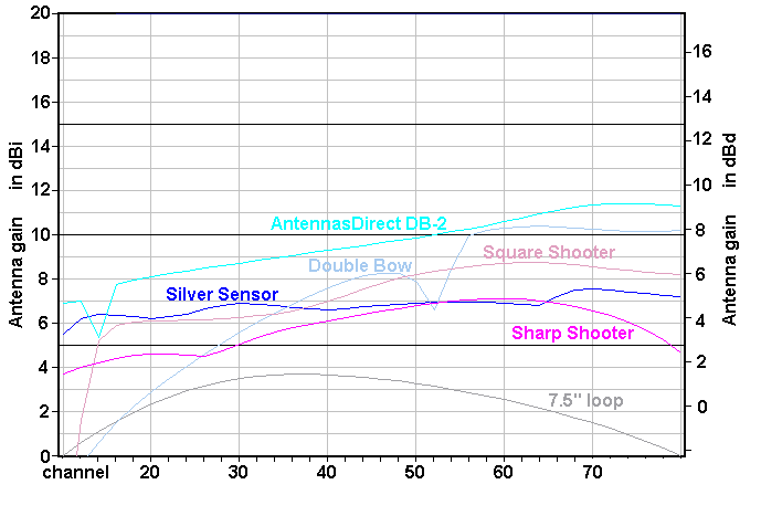
http://www.hdtvprimer.com/ANTENNAS/comparing.html
shows how the gain varies by channel for the common antenna types.
Antenna
gains are usually specified in dBd or dBi. If the
gain is specified as “X dBd”, that means that the
antenna is X dB better than a half-wave dipole.
“X dBi” means X dB better than an isotropic
antenna. A dBi
figure is always 2.15 dB higher than a dBd
figure. (That is, the gain of a
half-wave dipole is 2.15 dBi.)
Manufacturer’s
gain specs are notoriously unreliable. Buyers
beware!
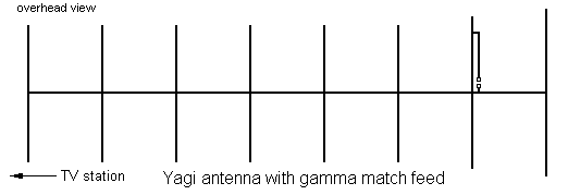
Gamma match
- This is a geometry that allows
the driven element to be connected directly to a 75-ohm coaxial cable, no balun needed. Its
problem is that it works well for only one channel. Even makers of single channel Yagis tend to avoid this solution since single channel Yagis are often used for viewing other channels that are
strong.
Ganged
antennas (see Stacked antennas)
Ghosts (see Multi-path interference)
Ground
plane antennas (see Vertical antennas)
Guy wires
- Guy wires are support wires
that hold the mast up. They are usually
necessary when the mast exceeds 12 feet in length. In most places, the mast will eventually face
an 80 mph wind. (West Coast antennas
don’t see more than 60 mph.)
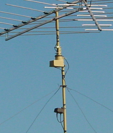
Since guy wires are usually steel they can disrupt the
antenna, lowering its gain. To avoid
this, keep the attachment point at least 4 feet below the VHF antenna boom (2
feet for UHF). If this is impossible,
guys made from plastics are a possibility (Dacron, Kevlar, etc.), but
stretchiness is a problem, along with cost and ultraviolet susceptibility.
HDTV antennas
- An antenna made for analog TV
will work fine for DTV. There is nothing
different about an antenna for DTV or HDTV.
Unscrupulous people have labeled their antennas “HDTV Antennas” as a
marketing ploy. The honest antenna
makers have had to re-label their products likewise to avoid losing sales.
Impedance
- A resistor limits current
flow. Resistance is defined by
Ohm’s Law: voltage = resistance * current. Likewise, reactance limits current
flow. Reactance is somewhat like
resistance, but it describes what coils and capacitors do. Reactance is sort of a phase-shifted
resistance, and the reactance of a device changes with frequency.
In
a circuit that has both resistance and reactance, the term impedance is
generally used. Impedance equals
resistance plus reactance.
Resistance
and reactance are so different from each other that they cannot actually be
added together. So impedance is a
two-part number in which the resistance and reactance are kept separate. It so happens that resistance and reactance
obey the arithmetic of complex numbers (numbers with real and imaginary
parts). Thus impedance is commonly
expressed as a complex number:
Resistance is the real part, reactance is the imaginary part. Be aware that electrical people often use “j”
instead of “i” to designate the imaginary part.
Thus
“impedance” is a generalized version of the concept of “resistance”, and it can
be used in place of the word resistance when there is no reactance. (It is not wrong to do so, but it can confuse
some.)
Adding
more confusion, the word “impedance” is sometimes a one-part number in which
the resistance and reactance have been “combined”, but this is less general and
less common. This number expresses the
net magnitude of the impedance, but the phase information has been thrown
away. You must figure out from the
context which version of “impedance” is being used.
Transmission
lines have a property called their characteristic impedance. See Transmission lines. See “Terminators for 75-ohm lines”. The characteristic impedance is usually 75
ohms (actually 75+0i) for coaxial lines and 300 ohms (actually 300+0i) for
twin-lead.
Antennas
have a terminal impedance. Matching this
impedance to the line is important. See
“Mismatch between antenna and feed-line”.
Formulas:
Inductive reactance: X=w*L
Capacitive reactance: X=-1/(w*C)
Impedance (2-part): Ż=R+X*i
Impedance (1-part) mag(Ż)=![]()
Where:
R is resistance in Ohms
L is inductance in Henrys
C is capacitance in Farads
X is reactance in Ohms
Ż is impedance (2-part) in Ohms
f is the frequency in Hertz
w=2*p*f
Inductors
(coils and transformers) - When
a wire carries current, there is energy stored in the magnetic field around the
wire. Coiling the wire magnifies this
effect. Energy entering or leaving this
field affects the circuit. Inductance is
a measure of the coil’s effect on the circuit.
The
effect of inductance is proportional to frequency. At TV frequencies, even the minuscule
inductance of a straight piece of wire becomes important.
A
transmission line (coaxial or twin-lead) is a geometry in which the inductance
and capacitance cancel each other out, allowing an unimpeded energy transfer
for long distances.
Indoor antennas
- In good-signal areas, small
low-gain antennas may work fine. Indoor
antennas nearly always work up to 10 miles from the transmitter. They often work up to 20 miles for people who
live on hillcrests, and sometimes 30 miles if the transmitting tower is visible. But if http://www.antennaweb.org
says you are not a candidate for an indoor antenna then don’t waste your time
and money on this. The most basic
antenna is rabbit ears with a UHF loop. If
that doesn’t work then you should consider a disk antenna in the attic or
something on the roof.
If
you are a renter then you might have to learn to live with indoor
antennas. A popular indoor antenna is
the Silver Sensor (ZHDTV1, UHF only), available from Amazon.com and
others. It is also a superb looking
antenna that will actually dress-up your living room.
The
highest performing indoor antenna is a two-bay (UHF only). This is an outdoor antenna, but it is small
enough to use indoors. It is big, 13”x19”,
and not especially pretty, but if you are desperate, some sacrifices are
acceptable. You will have to invent some
kind of a stand for it. Two-bay antennas
are made by Channel Master (4220) and by AntennasDirect.com (DB-2).
You
might benefit from putting the antenna on a longer cable so you can search the
room for the strongest spot. The best
spots are usually pointing out a window in the direction of the stations.
A
preamplifier will probably help. The
only ones you should consider are the amplifiers made by Channel Master (Titan
or Spartan) and Winegard (AP series). You probably can’t determine the noise figure
for your receiver. If it is below 3dB
then a preamplifier will not improve anything.
So make sure you can return the preamplifier if it proves to be of no
benefit.
Probably
the best a renter can do is get a Channel Master 7777 amplifier, connect a
two-bay to its UHF input, and connect rabbit ears to its VHF input. If you are desperate to get a difficult VHF
channel, get a 5-element single channel Yagi and
suspend it a few inches below the room ceiling.
In-line amplifier
- One hundred feet is normally
the longest RG6 allowed for satellite dishes.
If you can’t avoid a longer run then you need an in-line amplifier. These small units take DC power from the coaxial
cable, and do not interfere with the DC or 22kHz tone that the receiver sends
to the dish. Place the amp at about the
midpoint of the cable. (You need one
in-line amp for every 100 feet of cable.)
Interference
- Common sources of interference
include:
·
Adjacent
channel interference (a very strong station one channel up or down). R1
·
Co-channel
interference (two weak stations on the same channel). R1
·
Multi-path
interference (usually caused by the direct path being blocked). R1,R2
·
A
very close transmitter (a neighborhood FM station, police station, taxi
company, etc.). R1,R3
·
An
industrial noise source (a factory, a clinic, a malfunctioning power
transformer). R1
·
Household
appliances. R4
·
Light
dimmers. R4
·
Fluorescent
lights. R4
Remedies:
R1 – See “Nulls in radiation pattern”.
R2 – See “Multi-path interference”.
R3 – See Overload.
R4 – Try one of these:
·
Try
fixing or replacing the device.
·
Try
replacing the device with a device containing some RF filtering.
·
Try
putting an RF noise filter on the power cord of the bad appliance.
·
Try
putting an RF noise filter on the power cord of your TV.
·
If
the TV and the appliance are on the same house circuit breaker, move one to a
different breaker.
Appliance
noise -
Household motors and fluorescent lights often produce noise of the “120
sparks per second” variety. If you tune
to an analog station (especially channels 2-6) you may see intense sparkles
that are somewhat confined to a broad horizontal band. If so, you must find the appliance and fix it
or replace it. Identifying the appliance
is sometimes difficult. You might have
to shut off the house circuit breakers one at a time, watching to see when the
sparkles go away. If every breaker but
the TV is off and every appliance on that breaker but the TV is off and the
sparkles remain then the noise source is either in a neighbor’s home or is a
bad transformer on a utility company pole.
(If you can walk around with a portable AM radio tuned to an unexplained
buzzy hum, you might be able to further isolate the
offending device.) If the source is in
your neighbor’s home, brush up on your diplomatic skills. If it is the utility’s transformer, call
them. They are obligated to fix it.
Ionosphere
- The ionosphere is a charged
layer of the atmosphere that can reflect radio waves. Actually it is a series of layers from 30-275
miles in elevation. It enables
communication beyond the horizon for a band of frequencies, and with multiple
reflections can reach half way around the globe. What those frequencies are depends on the
time of day, the time of year, and time within the 11-year sunspot cycle.
These
“skip” frequencies rarely go above 30 MHz and normally play no part in TV
reception. On rare occasions they will
go above 50 MHz, allowing the signals of channels 2, 3, and 4 to travel far,
allowing distant analog channels to be watched.
But this also allows atmospheric noise to travel far, so getting a
digital lock on a distant DTV channel is unlikely. Thus the most likely consequence of the
ionosphere is to occasionally kill a DTV channel 2-4 that you normally get
weakly.
Isotropic
antenna - This
is an antenna with equal radiation (reception) in every direction.
Nobody
actually wants one of these. It is
mainly a concept for comparison. For example,
if an antenna is rated at 7 dBi, that means it
is 7 dB better than an isotropic antenna.
Jack - A jack is a female connector.
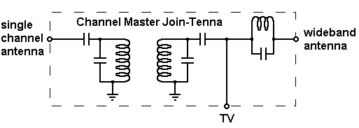
Join-Tenna -
These devices, made by Channel Master, are single channel diplexers
(combiners). They permit a single
channel antenna to share a feed-line with a wideband antenna. However they mess up reception for the
adjacent channels. Thus a Join-Tenna cannot be used for a channel adjacent to another
channel you want. (Since there are gaps
between channels 4-5, 6-7, and 13-14, this restriction does not apply to them.)
The
Channel Master website says Join-Tennas are available
only for channels 6-69. But units for
2-6 are sometimes findable. Join-tenna is missing from the new Channel Master catalog, so
these devices might not be available much longer.
There
is a unique Join-Tenna for each VHF channel. But UHF Join-Tennas
are adjustable, and there are just three of them for covering 14-29, 30-49, and
50-69. The seller will adjust it for
you. But they tend to be a little slow,
so acquiring one of these can take some time.
It is usually not practical for you to adjust it yourself.
Lightning
arrestor - A
lightning arrestor is a device that protects the equipment. It has a set of points or gas-discharge
devices that will arc-over when a high voltage is present. A lightning arrestor is important when the
feed-line is twin-lead. But coaxial
systems don’t usually have lightning arrestors because the center conductor
rarely acquires a high voltage, and the shield conductor is usually grounded
directly.
Log-Periodic
antenna (Log Periodic Dipole Array, LPDA) - The LPDA has several dipoles arranged in
echelon and criss-cross fed from the front. The name comes from the geometric growth,
which is logarithmic.

This
is a very wideband antenna of medium gain.
Usually only about three of the dipoles are carrying much current. The other elements are mostly inactive. As frequency increases, the active elements
“move” toward the front of the array.
Most VHF antennas are LPDAs.
TV
LPDAs come in two types: straight and Vee. The Vee type (LPVA)
has a very slightly higher gain for channels 7-13. The straight type has nulls 90° to each side that can be used to
cancel out a ghost, but the Vee type has less overall
radiation to the sides.
LPVA
(see Log-Periodic antenna)
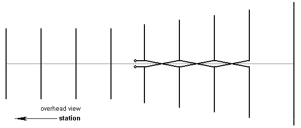
Log-Yag
antenna - This
hybrid antenna is an LPDA with some Yagi elements
added. It is a good wideband antenna and
is a common VHF antenna. Example: Winegard YA-1026.
Long-wire antenna
- A long-wire antenna is long, but
of no specific length or geometry.
Long-wire antennas are used for long distance reception on the AM and
short-wave bands, but are seldom used above 20 megahertz. This is not a good TV antenna because it is
unpredictable and usually has low gain.
Loop antenna
- Although a loop antenna will
work at any frequency (if the loop is the right size), for TVs it is only
common as a UHF antenna. It is a weak
antenna, comparable to a single dipole.
The performance of a 7.5-inch UHF loop antenna is described at http://www.hdtvprimer.com/ANTENNAS/comparing.html
.
LNB (Low Noise Block-converter), LNBF
- An LNA is a low-noise
amplifier. An LNB is an LNA plus a
Block converter circuit that shifts the frequencies downward. A DirecTV LNB shifts the Ku band frequencies
12.2-12.7 GHz down to 950-1450 MHz. This conversion is necessary because
satellite frequencies will not travel very far in ordinary coaxial cable.
An
LNBF is an LNB plus a Feed horn assembly.
LNBs
and LNBFs can be found at the focus point of a satellite dish antenna.
Masts
- Radio Shack sells 1.25”
diameter masts that are convenient for many antennas. But if you put a heavy antenna like an 8-bay
on a ten-foot mast of this type, it will sway with the wind and break in a high
wind. Heavy gauge 1.5” masts are
generally available at stores that sell Channel Master or Winegard
equipment.
Matching
transformer (see balun)
Mismatch between antenna and
feed-line -
An antenna has an innate impedance measured in ohms. If this value is the same as the transmission
line’s characteristic impedance then the energy captured by the antenna will be
efficiently transferred into the transmission line. Otherwise a portion of the signal will be
reflected (retransmitted). The greater
the degree of numerical mismatch, the more that will be rejected by the line.
At
http://www.hdtvprimer.com/ANTENNAS/comparing.html
you will see raw gain and net gain graphs. By comparing these two graphs you can see the
degree of mismatch for some common antennas.
For channels where the net gain and raw gain are about the same, the
antenna is well matched. For channels
where the net gain is far less than the raw gain, the antenna is badly matched.
The
antenna impedance is usually not just resistive, but also includes a reactive
component (which means there seems to be a capacitor or coil in series with the
antenna) and the reactance tends to be the bigger problem. There are ways to cancel out this reactance,
and also adjust the resistance. But
making the antenna better matched at one channel will make it worse matched at
other channels, and there is rarely an overall improvement.
Presently
there is no hardware commonly available to change the match, except for some
indoor antennas. To perfect the match
for a given channel on an outdoor antenna requires the services of an engineer.
(The
impedance of a half-wave dipole is 75 ohms, while a folded dipole is about 300
ohms. Many people when they see these
general geometries assume the antenna is 75 or 300 ohms. That is usually not even close. The other elements have a huge affect on the
terminal impedance. A CM-4228 has an
impedance of 1000 ohms at channel 25, and 750 ohms at channel 58, yet a 300-ohm
balun is a good overall match. Guessing the impedance from “inspection” is
something this author will not even attempt.)
Multi-path
interference - This
is a problem which, if severe, can prevent DTV reception even if the signal is
strong. The signal is reaching the
antenna by more than one path due to diffraction around hills and trees and
sometimes reflections off of structures.
There
are two distinct categories of multi-path interference. The first is “short delay” multi-path, delays
of less than about 20 nanoseconds. On
analog channels there will be no visible ghosts.
Short
delay multi-path - This
is always caused by something directly in front of the antenna. One common cause is a tree in front of the
antenna. There will be chaotically
overlapped signals behind a tree. This
will mainly affect UHF reception. The
solution is to relocate the antenna (or cut down the tree). If the antenna stays behind the tree, you
will likely see dropouts on UHF channels when the wind blows. And that’s for strong-signal areas. In weak-signal areas you will likely get no
UHF reception at all behind a tree.
The
other common cause is an irregular horizon line (structures and trees in the
distance). These will cause overlapping
fields, which will result in a regular pattern of strong and weak spots. For UHF, moving the antenna right or left
three feet or so can make a huge difference.
Moving the antenna is usually the solution. Unfortunately a strong spot for one channel
can be a weak spot for a different channel.
The same phenomenon happens for VHF, but since wavelengths are ten times
as big, the strong and weak spots are ten time further apart, so moving the
antenna to a strong spot is often too far to be practical. For VHF the solution is usually a bigger
antenna. (The author faces a severe case
of horizon-induced multi-path. His UHF
strong spots are always about 12 feet apart, but they can move with the
weather. His solution: He erected two UHF antennas 6 feet apart,
selected by a switch. Whenever one
antenna is in a weak spot, the other is guaranteed to be in a strong spot, so
at least one antenna always works.)
Long
delay multi-path - This
is caused by a large obstruction like a hill or a large building. If you tune in an analog channel close in
frequency and from the same direction, you will see ghost images. The offending signals are approaching the
antenna mostly from the sides, but also in rare cases from the rear. Actually all analog images have these ghosts,
but without the direct path blocked they are too dim to see.
One solution is to move the antenna to a new spot where
signals from the offending directions are less strong. A move of 20 feet or more will likely be
necessary.
The other solution is to select an antenna with little or
no reception in the offending directions.
There are two workable strategies here.
If the analog channels show one really strong ghost (and maybe a number
of weaker ones) then selecting an antenna with a null will work. See “Nulls in radiation pattern”. Otherwise an antenna with minimum radiation
to the side and rear is the way to go.
The higher the antenna’s gain, the less reception it will have to the
side. (More advice on multi-path can be
found at http://www.hdtvprimer.com/ANTENNAS/silver.html
. Although that article is written for
the Silver Sensor antenna, the same principles apply to larger antennas.)
Multi-switches
for DBS systems -
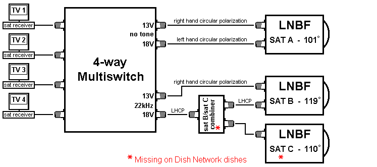
Every
DBS satellite system has a multi-switch.
Often it is mounted within 3 feet of the dish. Other times it is packaged with the three
LNBFs in a single large head assembly.
Basically it connects each TV to one of four lines from the LNBFs. Some multi-switches will also amplify the
signal. Multi-switches come in
1-receiver, 2-receiver, 4-receiver, 8-receiver, and other configurations.
When
the user selects a channel, the satellite receiver must figure out which
satellite and transponder the channel is on and whether the transponder has
left or right circular polarization. (A transponder
is like a large channel. Each
transponder carries several stations.
Consecutive transponders have alternating polarization, which makes it
easier for the receiver to separate the transponders.) The receiver selects the satellite by placing
(or not) a 22-kilohertz tone on the coaxial cable. It selects the polarization by placing either
13 volts DC or 18 volts DC on the coaxial cable. The multi-switch uses this DC both as a
signal and as a source of power for itself and the LNBFs.
For
DirecTV, the third satellite carries only a few transponders, and the combiner
maps those into unused transponder frequencies of satellite B. Thus the receiver functions as if there are
only two satellites.
(This
article needs updated for Ka band satellites.
Rumors are that Ka band transponders are down converted to frequencies
above and below the 900-1500 MHz frequencies used for Ku band, that a 4-way
multi-switch is always built into the dish, and that an 8-way outboard
multi-switch exists that can always adapt this 4-way output to feed 8
receivers.)
Noise/Noise figure/Noise factor
- For TVs there are two main
sources of noise:
1. Atmosphere noise. There are many types of sources for this
noise. A light switch creates a radio
wave every time it opens or closes. Motors
in some appliances produce nasty RF noise.
2. Receiver noise. Most of this noise comes from the first transistor
the antenna is attached to. Some
receivers are quieter than others.
Receiver
noise dominates on the VHF and UHF bands, and atmospheric noise is usually
insignificant.
The
noise figure and noise factor are the same thing, but the noise figure
is expressed in dB. Every amplifier has
a noise figure. The noise figure must be
subtracted from the antenna gain. Thus
the noise figure tells how much of the antenna gain you are throwing away by
not buying a quieter amplifier. The
amplifier in question is the OTA receiver or the mast-mounted amplifier,
whichever the antenna connects directly to.
Noise
management is discussed at http://www.hdtvprimer.com/ANTENNAS/basics.html
. If you do not manage the noise
properly, you might be throwing away a large portion of the antenna signal.
Nulls in radiation pattern
- Nulls in the radiation pattern
can be useful. If you rotate the antenna
so that a null points toward an interfering signal, that signal is
eliminated. Some interference situations
that might benefit from this trick include:
·
Adjacent
channel interference (a very strong station one channel up or down)
·
Co-channel
interference (two weak stations on the same channel)
·
Multi-path
interference (usually caused by the direct path being blocked)
·
A
very close transmitter (a neighborhood FM station, police station, taxi
company, etc.)
·
An
industrial noise source (a factory, a clinic, a malfunctioning power
transformer)
For
example, the Channel Master 4228 has nulls on both sides at 30 and 90 degrees:
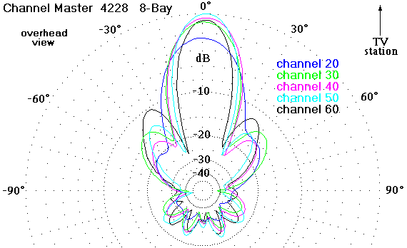
Yagi/Corner-reflector antennas have no
nulls. LPDA antennas have nulls at 90
degrees, but LPVA antennas have no nulls.
To make rabbit ears have nulls (at 90 degrees) lower them into a
straight dipole.
See
also The
Two-Antenna Trick (indoor version) and The Two-Antenna
Trick (outdoor version) . These
explain how to create a null in a controlled direction.
In
a multi-path situation, a null will work if there is only one strong
ghost. (Find an analog channel close in
frequency and from the same direction.
Examine it for ghosts.) If there
are multiple very strong ghosts then a better approach is a very high-gain
(very directional) antenna with little reception to the side or rear.
Omni-directional
antenna - This
is a non directional antenna. Its gain
is low, but if you are in a city and surrounded by stations, this might be the
perfect antenna. Common omni-directionals include these disk antennas:
·
Channel
Master 3000 SMARTenna, 22” circular VHF/UHF. The 3038 amplifier is optional.
·
Winegard
MS-1000 or MS-2000 MetroStar, circular VHF/UHF. Amplifier optional.
·
Radio
Shack 15-1634, 21” circular VHF/UHF.
Amplifier included. (Since Radio
Shack amplifiers tend to be noisy, the author would probably avoid this
antenna.)
The gain
of these antennas is no better than that of a typical indoor antenna, but if
you mount this unit in the attic or on the roof, you will likely see a
considerable improvement. And you won’t
have to re-aim it or endure dropouts when someone walks past the TV. Most people will benefit by getting an
amplified version, but if you are in a very strong-signal neighborhood, that
won’t be necessary.
An
important exception is if tall buildings block some stations. In this case you will likely have multi-path interference.
If you see strong ghosting on analog channels then you have multi-path and you
are not a candidate for an omni-directional
antenna. Most DTV receivers have trouble
with multi-path, even if the signal is strong.
You need a very directional antenna that can ignore signals coming from
the wrong directions.
Overload
- Signal amplifiers are supposed
to be linear. That is, the output is a
magnified but otherwise unaltered version of the input. But too much signal can make an amplifier
non-linear, usually clipping off the tops and bottoms of the sine waves. When this happens, all channels are
affected, not just the one that is too strong.
In fact, the too strong signal is usually not a TV station. A close FM station or police station is more
likely.
If
you add a good amplifier to your antenna system and your results get worse
instead of better then you have overload, and you need to reconsider more
carefully what you are doing.
Overload
never causes any equipment damage.
An
attenuator is a resistor network that can be used to reduce the gain of
an amplifier. 3 dB and 6 dB attenuators
are commonly available. If an antenna
system needs two amplifiers, where the output of one amp feeds into the other
amp, too much gain (overload) can result and an attenuator is usually the
simplest solution. If you don’t have two
amplifiers, it is unlikely that you will ever need an attenuator.
If
you are close to an FM station, there might be a narrow range between too much
and too little amplifier gain. You can
make that range larger by using an amplifier with an FM trap or by using
a more directional antenna. VHF
preamplifiers usually include FM traps that can optionally be disabled. Freestanding FM traps are also available. FM traps can either cover the entire FM band
or can be single frequency traps that you tune to the offending station. The former are less effective and tend to
attenuate channel 6. If the FM station
is close enough you might need more than one FM trap.
Painting
an antenna -
Many people think TV antennas are unattractive. Will painting an antenna to make it less
visible affect the way it performs?
No. Dielectrics affect antennas,
but a layer of paint is too thin for this effect to be significant. Many cell phone antennas are painted
black. HAM radio operators often use
long-wire antennas that have an enamel coating.
Don’t
use a paint that has embedded metals (metallic flakes, red oxide, graphite,
carbon). Enamel paint is best. Rustoleum is a good
choice.
Do
not paint the terminals. Do not paint
the rivets that hold together the criss-cross feed
line of a log-periodic antenna.
Parabolic antenna (see Reflector antenna)
Parabolic
dish antenna (see Dish antennas)
Parasitic
elements -
Elements not connected to any feed-line are called parasitic
elements. They are generally divided
into two categories: reflectors and directors.
See Yagi antennas. See Reflector antennas. Despite having no connections, parasitic
elements carry a considerable current.
Plug - A plug is a male connector.
Polarization
- AM radio antennas are generally
some sort of vertical wire. This is
because AM radio waves have vertical polarization. Other directions are possible. Most TV signals have horizontal
polarization and thus require antennas with horizontal elements. The broadcaster chooses the
polarization. That decision reflects
what type of antenna is most convenient for that service and also how radio
waves behave at that frequency.
If
you hold an antenna perpendicular to the polarization of the signal, you will
receive no signal. The received signal
strength varies with the cosine of the angle of the antenna relative to the
signal polarization. (Reflections off
nearby objects commonly make this experiment imperfect.)
If a
transmitter uses two antennas, one vertical and one horizontal, the result is
most likely diagonal polarization, which the station could also produce
with a diagonal antenna. Vertical,
horizontal, and diagonal polarizations are examples of linear polarization. But if this station introduces a
quarter-cycle delay into one of these two antennas, the result is circular
polarization (or elliptical polarization if the two components are
not equal).
Circular
polarization can be visualized as a signal that spins as it moves through
space. But it is equally valid to think
of circular polarization as just two independent overlapping signals that have
linear polarizations that are perpendicular and have a quarter-phase shift.
Circular
polarization can be right circular or left circular. DBS satellites use circular polarization,
with adjacent channels using opposite spin.
A right circular antenna will ignore a left circular signal, and visa versa. DBS
satellites alternate the polarization to make it easier for the receiver
electronics to separate the channels.
A
linear antenna can be used to receive a circularly polarized signal, but half
of the transmitted power will be invisible to it. A circularly polarized antenna can be used to
receive a linearly polarized signal, but half of the received signal will be
retransmitted with the opposite linear polarization. Because of these problems, circular
polarization has not become popular for terrestrial radio services other than
FM broadcasting. A small percentage of
TV broadcasters use circular polarization, which improves reception in a moving
vehicle equipped with a vertical antenna.
Power Injector (see antenna amplifiers)
Preamplifier (see antenna amplifiers)
This page is part of “An HDTV Primer”, which
starts at www.hdtvprimer.com