8/14/08
A 16-Bay UHF Antenna
When two
identical antennas are mounted together (ganged) and pointed in the same
direction and wired together properly, there is a theoretical possibility of a
3 dB improvement. That is, twice the
signal power is delivered to the TV compared to what a single antenna would
do. In practice, 2.5 dB is readily
achieved, 0.5 dB being the typical loss in the combining device. But if the two antennas are pointed in
different directions (towards different stations) a 3.5 dB penalty for each
antenna is the likely result.
The above
statements are true regardless of whether the antennas have shared or separate
amplifiers. For a shared amplifier, if
the antennas point in different directions, half the power each antenna takes
in reflects off the combiner and is rebroadcast out the antennas. Why this doesn’t happen when they are pointed
the same way is harder to explain. (For
an explanation see Ganging
Antennas.)
For dual
amplifiers, when the antennas are pointed the same way, this signal is
increased by 6 dB but the noise is increased by 3 dB, so the overall
improvement is still 3 dB. (This comparison is
relative to the same circuit with one amplifier powered off.) When they are pointed differently, the 3 dB
noise increase causes a signal/noise ratio loss of 3 dB for both stations. Dual amplifiers will eliminate the 0.5 dB combiner
loss, but only if the amplifiers are closely gain-matched.
(Ganging
non-identical antennas is not recommended.
They would need to produce equal voltages, and adjusting out the phase
difference is not generally possible for all stations.)
Channel Master to
the rescue
Ganging a
pair of Channel Master 4228 8-Bays will give you probably the best UHF antenna
that a consumer can achieve with reasonable ease. The author discovered some extra problems
with the 32-bay described later, a project that should be attempted only by
people who love antennas.
If all your
weak stations are above channel 40 then ganging a pair of
Yagi/Corner-Reflectors would be smarter.
That project will not be described here, except to say:
- The AntennasDirect.com XG91 is
the most obvious candidate.
- They should be mounted with the
booms about 3.5 feet apart.
- For a side-by-side mounting,
boom-to-boom metal rods are forbidden in front of the reflectors. Instead mount each antenna on a 2-foot
vertical mast. The masts can be
connected together 2 feet below the booms.
The wires can run along the boom but should descend 2 feet before
turning parallel to the elements.
- For a one-over-the-other
mounting, angle the booms up to the skyline, and mount the top unit
rearward enough so that its phase is not “ahead” of the lower unit.
- All the principles described in
this chapter apply.
Your big
decision is deciding between a side-by-side mount and a one-over-the-other
mount.
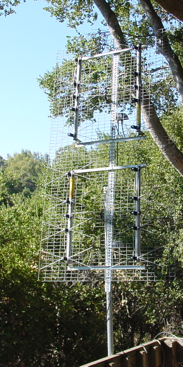
Side-by-side mount
The elevation
view of the radiation pattern is the same as for a single 4228. But in the view from overhead, the 16-bay is
2.1 times more directional. This could
be good or bad. There is no better
antenna for eliminating ghosts that arrive from near the front. But even a Channel Master rotor will have a
hard time hitting the correct direction.
(Radio Shack rotors need not apply.)
Some World War II radar antennas weren’t much different from this. Hopefully all your transmitting antennas are
in the same direction, either because they are on the same tower or because the
city is so far away. When a rotor is
required, the one-over-the-other mount is usually wiser. Usually side-by-side 4228s are positioned so
that the two screens just touch. But if
they are 1-1/2 inches apart then the mast can pass in front of the screens,
yielding a better weight distribution. A
few tie-wraps forcing the screens to touch will reduce radiation to the rear
and increase gain very slightly.
Mounting the two antennas farther apart will make the main forward lobe
even narrower, but the side lobes will grow in size.
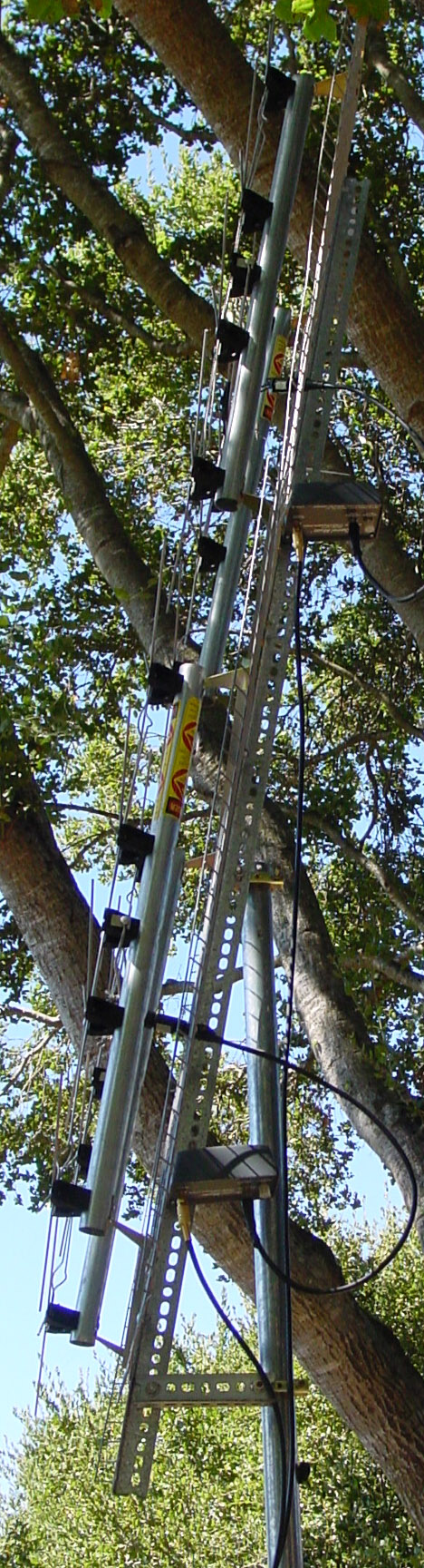
One-over-the-other
mount
In most
situations, a one-over-the-other is the wiser choice for a 16-bay. The radiation pattern viewed from above is
the same as for a single 4228. But in
the elevation view, the 16-bay is 2.2 times more directional. This is enough to require taking the skyline
elevation into account. The antenna
should be tilted up to point at the skyline (the distant horizon).
Some authors
will recommend that a motorized tilter be used since the angle of the incoming
signal can change from day to day. It
can. But high angle days are strong
signal days, and the loss of a dB won’t matter.
This author recommends a tilter only when a rotor must point the antenna
in different directions with different skyline elevations.
The simplest
mounting technique requires a single heavy angle-iron 65-70 inches long. Attaching it just below its midpoint to the
top of the mast will keep the assembly from being too front-heavy.
Mounting the
hardware
At 8 lb., the
4228 is a heavy antenna. Putting up two
of them requires a 1-½ inch, 16-gauge metal mast. (A Radio Shack mast will bend with the
breeze.) The total weight of the
antennas, mast, mounting irons, etc. will exceed 25 lb. Trying to erect it yourself on a sloped roof
is something akin to suicide, even without a wind. You need help. You need a large helping of good judgment. You need a rope around your waist so that you
don’t fall off the roof when the whole thing tips over. Some antenna adjustments will likely be
necessary, so don’t think you can put it up once and be done with it. Yagi/Corner-Reflectors weigh a lot less.
(The author has not tried a rotor mount and
doesn’t know for certain if the Channel Master rotor can handle this weight or
has the aiming accuracy required for a side-by-side mount. You need to discuss this with a knowledgeable
sales person or installer, but such people are rare. Rotors that handle more weight can be found
in HAM radio stores.)
Connecting them
together
The two antennas
must be phase-matched. This means that
the two signals must arrive at the combiner in phase. (a ±10° phase error is not a noticeable
error, but anything larger should be avoided.)
You do this by maintaining symmetry in the feed system. In other words, the wires for each antenna
should be identical in type and length.
The actual length is not critical.
If a ground
reflection causes one antenna to be phased ahead of the other, this should be
adjusted out by repositioning one antenna.
This is most easily done by finding a new skyline tilt angle. Simply adjust the tilt while watching the
signal strength. Different stations
could require different angles, so adjust it for your weakest station.
There is a
chance that you will mix up the polarities such that the two antennas subtract
instead of add. Doing this will result
in two forward lobes, reduced in size, with a null straight out the front. After the antenna is fully hooked up, you
should rotate the antenna to check for this pattern. If so then you have to reverse the
connections on one of the antennas. The
antennas come with a balun that has a “China” stamp on one side. I believe this stamp is the key to getting
addition on the first try.
There is no
point in building this antenna if you plan to use a Radio Shack amplifier. Their best amplifier will cancel out most of
the advantage of the second antenna.
Dual amplifiers
Having two
amplifiers eliminates the combiner loss, but requires you to find amps with
equal gain. The only procedure doable by
consumers that I can think of for adjusting the gains requires attenuators on
the outputs of the amplifiers: one fixed and one variable. But the variable attenuator might not pass
D.C. I am at a loss for suggestions,
other than bringing both coax lines into the house or putting a 120VAC socket
at the antenna.
Shared amplifier
The problem
here is finding a low-loss combiner.
Supposedly, combiners and splitters are different devices. While either will do the other’s job,
combiners are supposed to be lower loss.
(Splitters don’t have to be low-loss since they come after the
amplifier.) But the best device I have
found is a VHF/UHF splitter that is quite lossy above channel 50. I will continue to search. Watch this space.
Why this 16-bay
antenna might not work
The author’s
neighborhood has hot spots and cold spots, places where the signal strength is
strong or weak. This is a consequence of
overlapping fields. Being 40
miles from San Francisco and behind some hills, DTV reception is only possible
when the antenna is positioned in a hot spot.
These hot spots are 10-16 feet apart for any channel, and are in
different places for different channels.
If you have hot spots for any UHF channel then you will have hot spots
for all UHF channels (from the same direction).
The distance between hot spots is determined by the frequency, the
distance to the skyline, and the geometry of the ridgeline at the skyline. That ridgeline is producing the overlapping
fields.
If one 4228
is in a stronger field, then part of its signal will be retransmitted out the
weaker antenna. This loss may equal the
little bit of gain you had hoped for from the weaker antenna. You will likely find that two 4228s are no
better than one. This retransmission is
only avoided when both 4228s are in equal fields. (When dual amplifiers are used, the argument
sounds different but the result is the same.)
At the author’s home, the change in field strength in just 3 feet is
enough to wipe out most of the hoped for 3 dB gain when the antennas are
mounted side-by-side. Fortunately hot
spots are not generally spherical.
Rather, they tend to extend upward and forward more than they extend
laterally. So the one-over-the-other
configuration is much more likely to work in a neighborhood with hot spots
But there is
an exception to that. If the 16-bay is
close to the ground and the ground is bare extending toward the station, an
efficient ground reflection is likely.
This is another case of overlapping fields. But in this case, the hot spots are mainly
arrayed vertically. The hot spots are
likely close together vertically, but farther apart laterally. In this case, the side-by-side is the
configuration more likely to work. The
incoming wave is angled downward by only a couple of degrees, and so the ground
reflection occurs on ground that extends perhaps hundreds of feet toward the
station. If this ground is paved, dirt,
water, or a grass lawn, then the reflection is efficient and will produce
extremely weak cold spots. If it is
covered with weeds, shrubbery, trees, or somebody’s house then the reflection
is scattered too randomly to have any effect on UHF reception.
An alternate
explanation: (non-essential reading)
Two signals
pass through each other without interacting.
But an antenna will respond to the sum of the instantaneous signal
voltages.
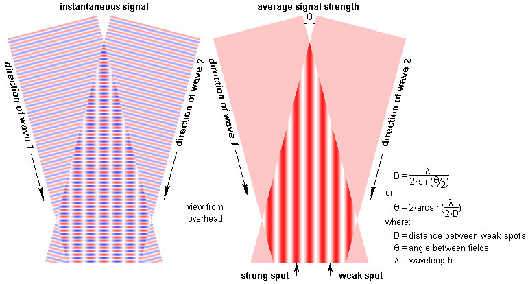
The fact
that the author’s hot spots are mostly orderly suggests that his neighborhood
has two overlapping fields. That is, the
signal is coming from two spots on the skyline.
How far apart are those spots?
This is found from the simple trig formula above.
l = 16.3 inches for channel 56
D = 11 feet for channel 56
Thus q = 7.1°
Thus the
signal is coming over the horizon at two spots 7 degrees apart. A 4228 in a hot spot can pick up both of
these signals. But a 16-bay side-by-side
is too directional to be aimed at both.
It will likely pick up twice as much of one signal but none of the
other, and thus will equal the performance of a single 4228.
This seems
like a completely different explanation based on a different phenomenon, but in
fact the two explanations are equivalent.
If you want
to explore the locations of your hot spots, a Silver Sensor on a 10-foot pole
is a good method. This antenna is small
enough to fit in any hot spot, and probably strong enough for a digital-lock in
a hot spot for your strongest station.
If possible, work at about the elevation where you plan your permanent antenna. You will need a monitor positioned there so
you can see the signal strength from the receiver. The distance between the hot spots will be
roughly the same for all channels.
If your hot
spots are too small both vertically and laterally, then a 16-bay might be out
of the question. Your option then is to
put each 4228 in its own hot spot. But
this only works for one channel.
You might
curse your bad luck if you find you have hot and cold spots. But you would be looking at it wrong. In fact, your neighborhood is concentrating
the signal for you. An antenna in a hot
spot can be up to 6 dB smaller than it would need to be in a “flat”
neighborhood. Now, if only the hot spots
never moved. But, that is another story…
Another reason this
16-bay antenna might not work
Let’s say you
are 20-miles from the station but behind a big hill. Your 4228 mostly works, but you see some
dropouts randomly. A 3 dB improvement
will likely solve your problems.
But beyond 40
miles, weather affects UHF considerably.
A 3 dB improvement will make some of the dropouts go away, but weather
can always get worse. Every antenna
improvement will help. But beyond 60
miles, it might not be possible to eliminate 100% of dropouts no matter how
good your antenna is. Beyond 60 miles,
solid reception on 9 out of 10 days is generally a good result.
This page is part of “An HDTV Primer”, which
starts at www.hdtvprimer.com